


July 2013
more quick guides @ www.farmscanag.com/jackal
AM-Jackal-2
12
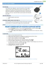
Tacho/RPM Meter Setup (Wizard)
TACHO/RPM METER SETUP (WIZARD)
DESCRIPTION
The Jackal can display a RPM (Revolutions per minute) Useful for
monitoring fans or shafts.
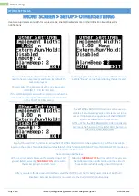
SENSORS REQUIRED
Sensor pickup 2 or 3 wire
Magnet for use with 2 wire or bolt head if using a proximity
AVAILABLE CONNECTIONS (REFER PAGE 3)
This setup section assumes that physical wiring for the required sensors have been completed. If not please
refer to page 3 on wiring requirements.
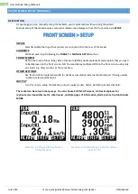
SETUP
FRONT SCREEN>SETUP>WIZARD>TACHOMETER
1.
Using the
NAV KEYS
select the current port the sensor input is connected to & press NEXT
2.
Press
EDIT
(to enable the port)
3.
Using the
EDIT KEY
select
pulse/rev
(Pulse/Revolution)
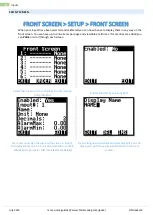
4.
Using the
NAV KEYS
scroll to
MANUAL RATIO
1.000000 & press
EDIT
5.
Enter the number of magnets or pickup location per revolution.
a.
I.e. If 2 magnets are installed change 1 to 2
6.
Press
EXIT
when done
7.
Press
NEXT
8.
Select
1: rpm
9.
You can now
EDIT
the audible alarm points for a
Min & Max
range to be notified of a problem
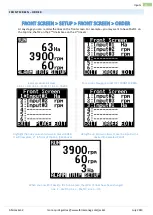
10.
Select
NEXT
11.
Create a name for your port if desired by pressing
EDIT
12.
Use the
UP/DOWN/LEFT/RIGHT
to change the letters. (Max 3 letters when in 3 up mode)
13.
Select
EXIT
when done
14.
Select
NEXT
15.
Select
EXIT
to return to the front screen to confirm setup
** Refer to page XX (Front Screen) to edit decimal places or to rename the port
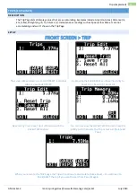
Example: 1UP monitoring 1 shaft
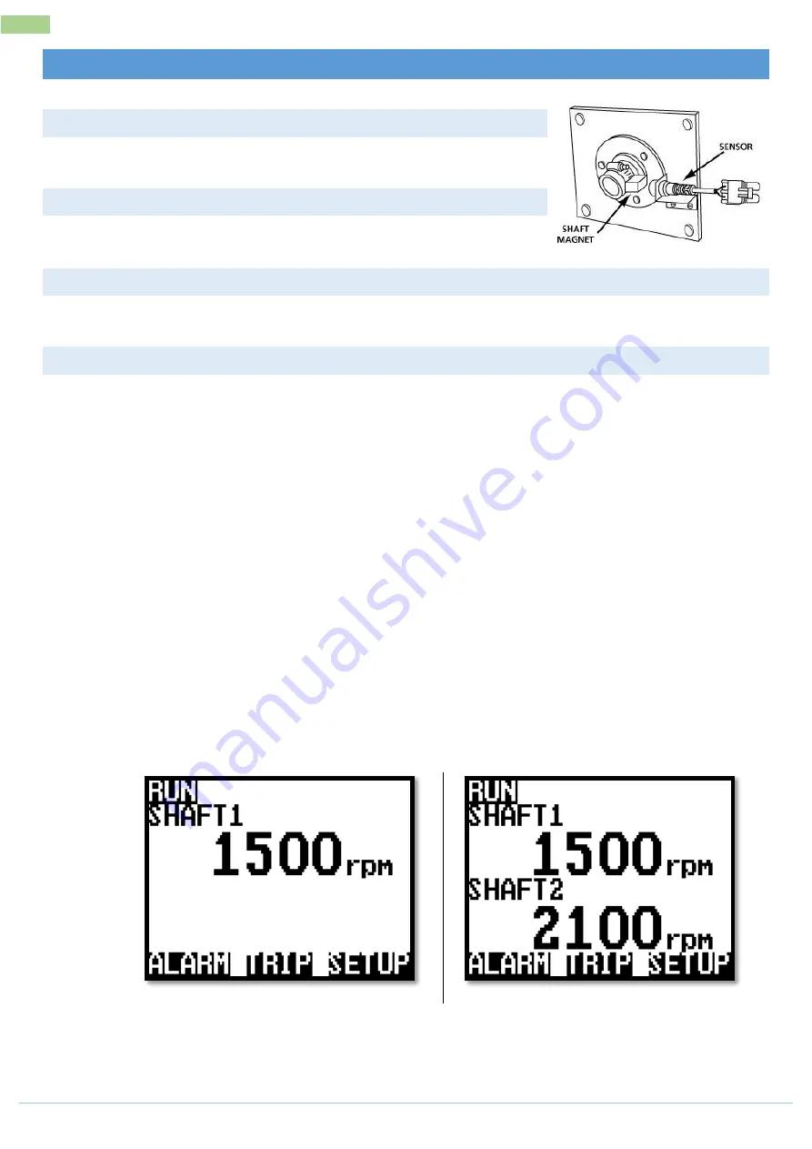
Example: 2UP monitoring 2 shafts
Содержание Jackal v2
Страница 1: ......


