background image

gnD 


d


Die vorliegende Anleitung wurde mit größtmöglicher Sorgfalt erarbeitet. Sollten Sie dennoch Fehler entdecken, 
bitten wir Sie, Fancom B.V. darüber zu informieren. 


Wenden Sie sich bei Fragen und für Hilfe an das Fancom Sales & Service Centre in Ihrer Nähe. 


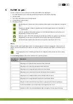
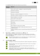
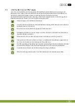
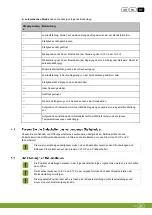
In dieser Bedienungsanleitung werden folgende Symbole verwendet: 


Tipps und Vorschläge. 


Beachten Sie alle Empfehlungen und zusätzlichen Informationen. 


Warnung vor einer Beschädigung des Produkts, wenn Verfahren nicht sorgfältig ausgeführt 
werden. 


Warnung vor einer Gefahr für Menschen oder Tiere. 


Gefahr von elektrischem Schlag. Gefahr für Mensch und Tier. 


Beispiel für eine praktische Anwendung der beschriebenen Funktion. 


Berechnungsbeispiel. 


Содержание IMS

Страница 1: ...G N D Gnd...

Страница 2: ...by Fancom For the latest information about product installation and operation please contact the customer service dept and or the technical service dept of the Fancom company concerned In spite of th...

Страница 3: ...connected actuator 10 4 2 Adjust the CLOSE position 11 4 3 Adjust the OPEN position if CLOSE already is adjusted 12 4 4 Adjust the PREDEFINED position 12 4 5 Complete adjustments 12 5 Extra possibilit...

Страница 4: ...Center The following symbols are used in this manual Tips and suggestions Note providing recommendations and additional information Warning indicating damage to the product if you do not follow proced...

Страница 5: ...IMS Ensure that the workplace is clean and dry Use correct wires as shown in the connection diagrams Make all wiring connections and check them before applying power Incorrect connections can cause p...

Страница 6: ...l all gland nuts after connection of the IMS to prevent entry of dust aggressive gases and or humidity You may connect to the IMS as an I O network module or as a traditional terminal Make sure that t...

Страница 7: ...n On Off On On 5 Off On Off On On 6 On Off Off On On 7 Off Off Off On On 8 On On On Off On 9 Off On On Off On 10 On Off On Off On 11 Off Off On Off On 12 On On Off Off On 13 Off On Off Off On 14 On Of...

Страница 8: ...Gnd 5 g 27 Off Off On Off Off 28 On On Off Off Off 29 Off On Off Off Off 30 On Off Off Off Off 31 Off Off Off Off Off...

Страница 9: ...f DIP switch 6 is set to NO measurement OFF or no settings have been communicated the IMS will control using the value set as the pre defined position Connection as a traditional terminal When used as...

Страница 10: ...ion Turn on the electricity after you have connected the IMS Switch on the power only after all cables have been connected correctly 1 Check whether the IMS has been connected correctly 2 Check whethe...

Страница 11: ...8 g The switch on the front of the IMS allows for Automatic regulation AUT manual closing opening or off 0 The manually operated selections work directly on the actuator bypassing the intelligent mod...

Страница 12: ...ter turning the IMS on three characters are first displayed in sequence These comprise the software version number one character per second During adjustment indications appear on the display The flas...

Страница 13: ...by the remote control 7 Actuator is standing still against a limiting switch A Stopped closing B Stopped opening C Additional delay of 2 seconds after a sending action U Due to problems the IMS now co...

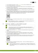
Страница 14: ...t necessary if a CPS is used Go to the next step 4 Press the pushbutton until the number 1 appears in the display and then release the pushbutton The IMS is now in the 1 adjustment mode After releasin...

Страница 15: ...inlet open position is correct 5 Press the pushbutton to confirm the setting The letter O now appears in the display This means that the adjustment was successful Is there something other than O in t...

Страница 16: ...connected the predefined position will be sought An L appears on the display Loss of power power failure When using an external emergency power supply UPS the 230 V AC will not be interrupted The UPS...

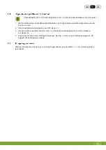
Страница 17: ...eter is used change over the connections of the inlet position feedback terminals 2 and 4 Not necessary if a CPS is used as position feedback 6 Switch on the power 7 Perform the adjustment procedure a...

Страница 18: ...e adjustment is not successfully done The notification of a retracted alarm can be deleted by pressing the pushbutton on the printout A control computer connected to the IMS via an I O network can tak...

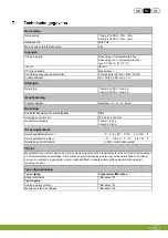
Страница 19: ...d IP54 Dimensions lxwxh 300x240x140mm Weight unpacked 1 phase 1 92 kg 3 hpase 2 28 kg Ambient climate Operating temperature range 0 C to 40 C 32 F to 104 F Storage temperature range 10 C to 50 C 14 F...

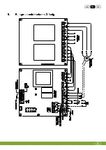
Страница 20: ...Gnd 17 g...

Страница 21: ...Gnd 18 g...

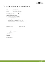
Страница 22: ...res that the IMS Complies with the provisions of the 1 Low voltage directive 2006 95 EC according to NEN EN IEC 61010 1 2010 2 EMC directive 2004 108 EC Emission according to NEN EN IEC 61326 1 2013 I...

Страница 23: ...productinstallatie en bediening neem contact op met de klantenservice en of technische serviceafdeling van de betreffende Fancom onderneming Mocht u onverhoopt toch een fout ontdekken dan vragen wij...

Страница 24: ...de verbonden aandrijfmotor af 10 4 2 Regel de gesloten stand af 10 4 3 Regel de open stand af als de gesloten stand al is afgeregeld 11 4 4 Regel de voorgedefinieerde stand af 12 4 5 Afregeling volto...

Страница 25: ...s Service Centre raadplegen In deze handleiding worden de volgende symbolen gebruikt Tips en suggesties Opmerking met aanbevelingen en aanvullende informatie Waarschuwing duidend op schade aan het pro...

Страница 26: ...voor een schone en droge werkplek Gebruik de juiste draden zoals getoond in de aansluitschema s Verbind alle draden en controleer de verbinding voordat u de stroom inschakelt Onjuiste aansluitingen k...

Страница 27: ...ation Zorg ervoor dat de IMS volgens de voorschriften goed en degelijk geaard is Bevestig de kabels zo dat deze niet beschadigd kunnen raken en eenvoudig vervangen kunnen worden in geval van defecten...

Страница 28: ...On On On Off 18 On Off On On Off 19 Off Off On On Off 20 On On Off On Off 21 Off On Off On Off 22 On Off Off On Off 23 Off Off Off On Off 24 On On On Off Off 25 Off On On Off Off 26 On Off On Off Off...

Страница 29: ...gNd 5 n...

Страница 30: ...OFF of als er geen instellingen zijn doorgestuurd gebruikt de IMS de waarde van de voorgedefinieerde stand als basis voor de sturing Aansluiten als traditioneel eindstation Bij gebruik als traditione...

Страница 31: ...luiting Schakel de stroom in nadat u de IMS hebt aangesloten Schakel de stroomvoorziening pas in nadat alle kabels correct zijn aangesloten 1 Controleer of de IMS correct is aangesloten 2 Controleer o...

Страница 32: ...aar aan de voorzijde van de IMS kan worden ingesteld op automatische regeling AUT handmatig sluiten openen of uit 0 De handmatige standen werken direct op de aandrijfmotor Daarbij wordt de intelligent...

Страница 33: ...t 2 2 V zijn Display Wanneer de IMS wordt ingeschakeld worden er achtereenvolgens drie tekens weergegeven Deze vormen het nummer van de softwareversie n teken per seconde Tijdens het afregelen verschi...

Страница 34: ...I O netwerk is uitgevallen Regel de eindschakelaars voor de gesloten en open stand van de verbonden aandrijfmotor af Indien nodig kunnen de eindschakelaars op de IMS worden aangesloten Verwijder v r a...

Страница 35: ...ling niet geslaagd Zet de fabrieksinstellingen terug als er geen verbetering plaatsvindt Zorg ervoor dat de gesloten stand is afgeregeld Zorg bij analoge sturing 10 0 V of 0 10 V dat de analoge uitgan...

Страница 36: ...2 Zet de handbedieningsschakelaar in een OFF stand O 3 Houd de drukknop ingedrukt totdat het cijfer 3 op het display wordt weergegeven en laat de drukknop vervolgens los 4 Druk op de drukknop om de i...

Страница 37: ...ellingen Wanneer op de drukknop wordt gedrukt wordt in dit geval L weergegeven op het display van de printplaat Als er geen temperatuursensor is aangesloten wordt de voorgedefinieerde stand aangenomen...

Страница 38: ...M 125 LM 250 wissel de twee fasen om bijv U1 en V1 5 LM 125 LM 250 wissel de aansluitingen voor het positieterugkoppelsignaal van de inlaat om klemmen 2 en 4 als een potentiometer wordt gebruikt Niet...

Страница 39: ...of gesloten stand is niet geslaagd Een melding voor het opgeheven alarm kan worden verwijderd door op de drukknop van de print te drukken Een regelcomputer die via een I O netwerk is verbonden met de...

Страница 40: ...Afmetingen L x B x H 300 x 240 x 140 mm Gewicht onverpakt 1 fasig 1 92 kg 3 fasig 2 28 kg Omgevingsklimaat Bereik bedrijfstemperatuur 0 C to 40 C 32 F to 104 F Bereik opslagtemperatuur 10 C to 50 C 1...

Страница 41: ...gNd 17 n...

Страница 42: ...gNd 18 n...

Страница 43: ...rmee dat de IMS Voldoet aan de bepalingen van de 1 De Laagspanningsrichtlijn 2006 95 EC conform NEN EN IEC 61010 1 2010 2 EMC richtlijn 2004 108 EG Emissienorm conform NEN EN IEC 61326 1 2013 Immunite...

Страница 44: ...ung nehmen Sie bitte Kontakt mit dem Kundendienst und oder dem technischen Service der zust ndigen Fancom Niederlassung auf Sollten Sie ungeachtet der Sorgfalt mit der die Anleitung verfasst worden is...

Страница 45: ...rbundenen Stellglieds an 10 4 2 Die Stellung CLOSE einstellen 10 4 3 Passen Sie die ffnungseinstellung an wenn die Schlie position bereits eingestellt wurde 11 4 4 Die Stellung PREDEFINED einstellen 1...

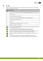
Страница 46: ...hrer N he In dieser Bedienungsanleitung werden folgende Symbole verwendet Tipps und Vorschl ge Beachten Sie alle Empfehlungen und zus tzlichen Informationen Warnung vor einer Besch digung des Produkts...

Страница 47: ...s der Arbeitsplatz sauber und trocken ist Die auf den Anschlussschaltbildern angegebenen Dr hte verwenden Alle Dr hte anschlie en und vor dem Anlegen von Strom berpr fen Fehlerhafte Anschl sse k nnen...

Страница 48: ...n Nach dem Anschlie en von IMS alle Stopfbuchsen versiegeln damit kein Staub keine aggressiven Gase und keine Feuchtigkeit eindringen k nnen Der IMS kann als E A Netzwerkmodul oder als klassisches Ans...

Страница 49: ...Aus Ein Aus Ein Ein 6 Ein Aus Aus Ein Ein 7 Aus Aus Aus Ein Ein 8 Ein Ein Ein Aus Ein 9 Aus Ein Ein Aus Ein 10 Ein Aus Ein Aus Ein 11 Aus Aus Ein Aus Ein 12 Ein Ein Aus Aus Ein 13 Aus Ein Aus Aus Ein...

Страница 50: ...gnD 5 d 27 Aus Aus Ein Aus Aus 28 Ein Ein Aus Aus Aus 29 Aus Ein Aus Aus Aus 30 Ein Aus Aus Aus Aus 31 Aus Aus Aus Aus Aus...

Страница 51: ...DIP Schalter 6 auf KEINE Messung AUS gesetzt oder wurden keine Messungen kommuniziert steuert der IMS mit dem Wert der vordefinierten Position Anschluss als klassisches Anschlussger t Bei einer Verwen...

Страница 52: ...ellen Sie eine Stromversorgung her nachdem Sie den IMS angeschlossen haben Schalten Sie die Stromversorgung erst ein nachdem alle Kabel ordnungsgem verbunden wurden 1 berpr fen Sie ob der IMS ordnungs...

Страница 53: ...chalter auf der Vorderseite des IMS kann Folgendes eingestellt werden Automatische Regelung AUT manuelles Schlie en ffnen oder Aus 0 Die manuelle Auswahl erfolgt direkt am Stellglied und umgeht das in...

Страница 54: ...Spannung muss 2 2 V betragen Display Nach dem Einschalten des IMS werden zun chst drei Zeichen nacheinander angezeigt Hierbei handelt es sich um die Softwareversionsnummer ein Zeichen pro Sekunde W hr...

Страница 55: ...roblemen nimmt der IMS die Regelung anhand der voreingestellten Stellung vor L Aufgrund des Ausfalls des E A Netzwerks l uft der IMS jetzt aufgrund der eigenen Temperaturmessungen unabh ngig Passen Si...

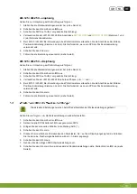
Страница 56: ...ie ffnungseinstellung Stellen Sie sicher dass die Schlie position korrekt ist 6 Dr cken Sie den Drucktaster zur Best tigung der Einstellung Auf dem Display wird jetzt der Buchstabe C angezeigt Dies be...

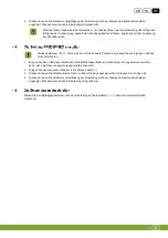
Страница 57: ...ssen Sie die folgenden Schritte nicht durchf hren 1 Bringen Sie den Lufteinlass mithilfe des Handbet tigungsschalters in die Stellung die angenommen werden kann wenn die Spannungsversorgung unterbroch...

Страница 58: ...Basis der Temperaturmessung und der Einstellungen In diesem Fall wird ein L in der Platinenanzeige angezeigt wenn die Taste gedr ckt wird Wenn kein Temperaturf hler angeschlossen ist wird die voreing...

Страница 59: ...richtung 4 Vertauschen Sie am LM 125 LM 250 die beiden Phasen z B U1 und V1 5 Bei LM 125 LM 250 Bei Verwendung eines Potentiometers vertauschen Sie die Anschl sse der Einlass Positionsr ckmeldung Klem...

Страница 60: ...ch Die Benachrichtigung ber einen zur ckgenommenen Alarm kann durch Bet tigung des Drucktasters an der Druckausgabe gel scht werden Ein ber ein I O Netzwerk an den IMS angeschlossener Regelcomputer ka...

Страница 61: ...ssungen LxBxH 300 x 240 x 140 mm Gewicht ohne Verpackung 1 phasig 1 92 kg 3 phasig 2 28 kg Umgebungsklima Betriebstemperaturbereich 0 C bis 40 C 32 F bis 104 F Lagertemperaturbereich 10 C bis 50 C 14...

Страница 62: ...gnD 17 d...

Страница 63: ...gnD 18 d...

Страница 64: ...Erkl rt hiermit dass der IMS Die Bestimmungen erf llt von 1 Niederspannungsrichtlinie 2006 95 EG gem NEN EN IEC 61010 1 2010 2 EMV Richtlinie 2004 108 EG Emissionen gem NEN EN IEC 61326 1 2013 Immunit...

Отзывы: