


Fancom 743
INSTALLER: 5. System settings
11
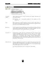
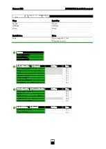
Counts
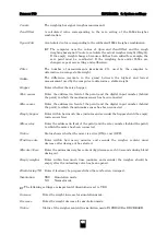
The weighing bar signal (rough measurement).
Zero/Offset
A calculated value corresponding to the zero setting of the ILM.x/weigher
combination.
Span (Cal.)
A calculated value corresponding to the calibrated ILM.x/weigher combination.
The computer uses the values of
Span
and
Zero/Offset
and the rough
weighing bar signal
Counts
to calculate the actual weigher weight (
Weight
).
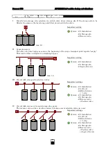
If the empty weight changes, because a lid has been added for example, the
zero point must be re-adjusted. If the weighing bars and/or ILM.x are
changed, repeat zero setting and calibration.
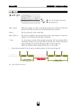
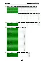
Filter
The number of measurements (maximum 25), used by the computer to
determine an average stable weight.
Stable
The difference (accurate to the gram) between the highest and lowest
measurement used by the computer to determine a stable weight.
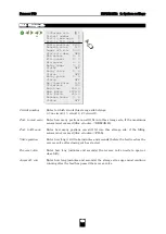
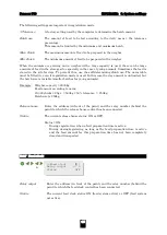
Hopper
Enter whether there is a hopper.
Max. sensor
Enter the address (in front of the point) and the digital input number (behind
the point) to which the maximum sensor has been connected.
Min. sensor
Enter the address (in front of the point) and the digital input number (behind
the point) to which the minimum sensor has been connected.
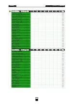
Empty hopper
Enter within how much time (minutes and seconds) the hopper should be empty
(min. sensor free)
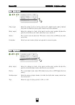
Mixer relay
Enter the address (in front of the point) and the relay number (behind the point)
to which the mixer has been connected.
Status
Status shows whether the mixer is active (ON) or not (OFF).
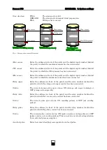
Wait time dec.
Enter within how many minutes and seconds the weigher content must
decrease after dosing out has started.
Min.dec./30sec
Enter the minimum weigher content (kg) decrease each 30 seconds during blend
dosing out.
Empty weigher
Enter within how much time (minutes and seconds) the weigher should be
empty after the unloading valve has been opened.
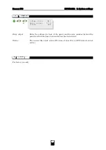
Block during TR
Enter if feed may be prepared when there is feed on transport.
Simulation
YES Simulation mode
NO
Normal mode
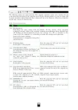
The following settings are important if
Simulation
is set to YES.
Increase
Enter the weight increase for simulation mode.
Decrease
Enter the weight decrease for simulation mode.
Status
Status of the weigher content in simulation mode: INCREASE or DECREASE.
Содержание 743
Страница 1: ...GB 743 INSTALLER MANUAL VERSION C3...
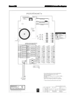
Страница 28: ...Fancom 743 APPENDIX 4 Connection diagrams...
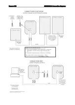
Страница 29: ...Fancom 743 APPENDIX 4 Connection diagrams...
Страница 30: ...Fancom 743 APPENDIX 4 Connection diagrams...
Страница 31: ...Fancom 743 APPENDIX 4 Connection diagrams...


