background image


Contents 

INTRODUCTION ...................................................................................................................................... 4


Manual Overview................................................................................................................................... 4


UPS Features ........................................................................................................................................ 4


SAFETY .................................................................................................................................................... 6


PRODUCT OVERVIEW ............................................................................................................................ 8


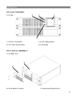
Operating Conditions............................................................................................................................. 8


UPS Circuit Descriptions ....................................................................................................................... 9


Inspecting the Equipment .................................................................................................................... 10


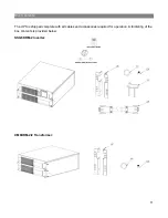
Box Contents ....................................................................................................................................... 11


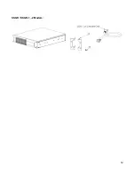
UPS Overview ..................................................................................................................................... 13


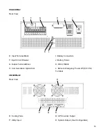
UPS Component Overview ................................................................................................................. 16


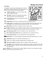
Display & Controls .................................................................................................................................. 17


Getting Started ........................................................................................................................................ 19


Installation Environment ...................................................................................................................... 19


Rackmount Installation ........................................................................................................................ 20


Battery Bank Installation...................................................................................................................... 23


Electrical Wiring................................................................................................................................... 24


Output Configurations ......................................................................................................................... 26


UPS Start-up Procedure...................................................................................................................... 28


UPS Operation ........................................................................................................................................ 30


Operating Modes ................................................................................................................................. 30


Communications ..................................................................................................................................... 36


Communication Features .................................................................................................................... 36


Dry Contact Relay Cards..................................................................................................................... 37


Batteries .................................................................................................................................................. 39


Safety .................................................................................................................................................. 39


Battery Information .............................................................................................................................. 40


Battery Pack Replacement .................................................................................................................. 42


Troubleshooting ...................................................................................................................................... 43


Alarms ................................................................................................................................................. 43


Technical Support ................................................................................................................................... 46


Contact Us .......................................................................................................................................... 46


Warranty ................................................................................................................................................. 47


Содержание SSG6KRM-2

Страница 1: ...Falcon Electric Inc All other brand names and trademarks are the property of their respective owners The information and specifications stated in this document are subject to change without notice OM4...

Страница 2: ...2...

Страница 3: ...ls 17 Getting Started 19 Installation Environment 19 Rackmount Installation 20 Battery Bank Installation 23 Electrical Wiring 24 Output Configurations 26 UPS Start up Procedure 28 UPS Operation 30 Ope...

Страница 4: ...th robust components and materials the SSG assures reliable operation and a long service life in stressful environments It is a true on line industrial UPS 12 year rated batteries cut service costs Th...

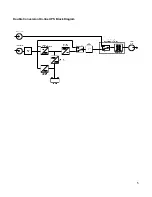
Страница 5: ...5 Double Conversion On line UPS Block Diagram...

Страница 6: ...reduce the risk of fire or electrical shock replace only with the same type and rating of fuse CAUTION To reduce the risk of fire connect only to a circuit provided with 30 amperes maximum branch circ...

Страница 7: ...7 Symbols Important Instruction Special Note Recycle Do not dispose with ordinary trash...

Страница 8: ...al scientific or data processing class equipment The SSG Industrial UPS requires minimal maintenance or monitoring if the documented installation environmental and operational specifications have been...

Страница 9: ...C converter In both modes of operation the UPS inverter is online and continuously generating clean regulated AC power to the load The Isolated Gate Bipolar Transistor IGBT Pulse Width Modulation PWM...

Страница 10: ...nsformer box This switch serves to provide power to the connected equipment in case of UPS failure or maintenance is required Inspecting the Equipment Visually inspect the UPS for shipping damage If t...

Страница 11: ...11 Box Contents The UPS is shipped complete with all cables and accessories required for operation A full listing of the box contents is provided below SSG6KRM 2 Inverter XM6KRM 2 2 Transformer...

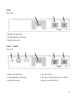
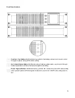
Страница 12: ...12 SSGR SSGR 1 2 Models...

Страница 13: ...nverter SSG6KRM 2 Front View A Function Test Button B Set Alarm Silence Button C Power Bypass Button D LCD Display UPS Transformer XM6KRM 2 2 Front MBS View M Removeable front panel N Maintenance Bypa...

Страница 14: ...put Terminal Block H Communication Option Slot I Battery Connectors J Battery Fuses K DB 9 RS232 L Remote Emergency Power Off R E P O Terminal XM6KRM 2 2 Rear View O Cooling Fans P Utility Input Q UPS...

Страница 15: ...ional Battery Connection 3 Battery Connection SSGR 1 SSGR 2 Rear View 4 Battery Circuit Breaker 5 Additional Battery Connection 6 Battery Connection 7 AC Power Switch 8 AC Power Cord Inlet with Fuse 3...

Страница 16: ...dule Input Circuit Breaker One or more protection devices provided to protect the UPS input from an over current condition Cooling Fan One or more devices provided to maintain the proper temperature o...

Страница 17: ...ell icon indicates the battery capacity The greater the battery capacity available the more internal bars will be illuminated Each bar represents 25 capacity Fan in high speed mode HS fan icon indicat...

Страница 18: ...ction setting Set Alarm Silence Button Multifunctional key disables audible alarm used to scroll through metered parameters and sets the desired programmed setting Power Bypass Button Multifunctional...

Страница 19: ...rack space Do not block air flow Allow a minimum of 3 inches 76 2mm clearance from the front and rear panel air vents Environment o Intended for use in a protected environment free from moisture flam...

Страница 20: ...the units to the rack rails They do not support the weight of the UPS transformer or battery bank Rack slides or shelves are required Reference the following procedure to install the UPS in a standard...

Страница 21: ...ion and disconnect the inner from the outer member Rack Section 4 For slide rail installation fasten the inner portion of the slide rail to the UPS on both sides with the screws provided 4 8 32 x 3 16...

Страница 22: ...S with inner parts attached into the slide assemblies You may need to depress the locking mechanisms on the inner and outer parts of the slide assemblies to allow the slides to retract The UPS should...

Страница 23: ...ks are shipped with the internal battery packs preinstalled 1 Remove the Battery Connector cover plates to expose the battery connectors as shown below 2 Assure the battery circuit breakers are in the...

Страница 24: ...commendations Please adhere to local and national electrical codes Model Maximum Current Conductor Selection 6kVA 30 Amps Input Use 10 AWG 75 C copper wire TRQ 4 4 IN LB 30 Amps Output Use 10 AWG 75 C...

Страница 25: ...25 SSG6KRM 2TXI With Transformer Module Warning Utility sources must be of the same phase...

Страница 26: ...26 Output Configurations 240V 120V Split Phase L1 to L2 240VAC L1 or L2 to N 120VAC Each 120VAC winding is limited to 50 maximum of total UPS output capacity Single Output Configuration 208 240VAC...

Страница 27: ...27 Single Output Configuration 120VAC...

Страница 28: ...n the ON up position 2 Turn on the input circuit breaker located on the rear panel of the UPS inverter module 3 Allow 30 to 45 seconds for the UPS to complete power on self test 4 Confirm the UPS disp...

Страница 29: ...then power on the load Turn off UPS Utility Power Available Warning Do not press any other buttons after the shutdown command has been initiated to prevent interruption fault alarm or unexpected outpu...

Страница 30: ...capacity As capacity decreases fewer bars will remain illuminated The charger icon is turned off and the UPS will emit a continuous audible beep sequence during battery mode operation Bypass Mode Byp...

Страница 31: ...battery backup is not required when equipment is drawing low current REPO Mode Remote Emergency Power Off A two pin normally closed connector is located on the rear panel of the UPS The connector is s...

Страница 32: ...ery Voltage Load Percentage Input Current Percentage Internal Temperature Celsius Output Current Use the set alarm silence button to scroll through the available meter readings Actual readings will va...

Страница 33: ...te battery capacity 1 While the UPS is operating in online mode press the set alarm silence button three times until the battery voltage metering is displayed 2 While the UPS is operating in online mo...

Страница 34: ...On 230V Off 220V On 208V Off 1 While the UPS is online simultaneously press the function test and set alarm silence buttons until an audible beep emits to enter the configuration mode 2 Use the funct...

Страница 35: ...35 Default Programmed Settings 230V Models Function Bit 6 5 4 3 2 1 0 N A N A N A N A N A N A N A N A Green Mode Disabled 230V Output...

Страница 36: ...e required is a 4 Pin USB Type A M connector 4 PIN USB Type B M connector The USB and RS 232 ports cannot be used concurrently Please follow the installation and setup instructions supplied on the sof...

Страница 37: ...n Jumper Designation Default Setting Definition J9 Summary Alarm 1 2 Contact Closed J10 Low Battery 1 2 Contact Open J12 UPS Model Selection 1 2 SSG Series J13 On bypass Alarm 2 3 Enabled DB 9 Pin Des...

Страница 38: ...r Designation Default Setting Definition J9 Summary Alarm 1 2 Contact Closed J10 Low Battery 1 2 Contact Open J12 UPS Model Selection 1 2 SSG Series J13 On bypass Alarm 2 3 Enabled Terminal Designatio...

Страница 39: ...t may be toxic CAUTION A battery can present a risk of electrical shock and high short circuit current The following precautions should be observed when working on batteries Remove watches rings or ot...

Страница 40: ...following precautions should be observed to maximize battery life Connect UPS to a properly rated outlet for at least 24 hours to ensure batteries are in a fully charged state prior to long term stora...

Страница 41: ...e The table below provides the typical battery service life during float trickle charge Ambient temperature greatly affects the overall battery life Temperature Period Years Float Charge 25 C 77 F 12...

Страница 42: ...left side first and battery support plate as shown Then remove the right side 2 Remove the battery packs Grasp each battery pack from the sides Do not place hands on rear 3 Install the replacement bat...

Страница 43: ...he utility power frequency Five short beeps continuously ___ UPS internal over temperature Cooling fan failure Check air vents for blockage Check fan operation Check ambient room temperature Six short...

Страница 44: ...attery disconnects are in place turned on UPS will not provide power to the load Output only present on one receptacle No output from any output receptacle Output fails as soon as load is connected Ch...

Страница 45: ...lity power surge Disconnect load from UPS output Restart UPS If error persists contact Falcon Electric Service Department 1 SOFT START FAULT CPU detects error due to excessive overload at start up aff...

Страница 46: ...n a Return Material Authorization number RMA along with return shipping instructions The RMA number issued must appear on the outside of the shipping carton The original shipping container must be use...

Страница 47: ...llation misuse or neglect ii unauthorized repairs or modifications or use of unauthorized parts iii acts or events outside of Falcon s control such as fire accidents impacts iv normal wear and tear su...

Отзывы: