10.0 PARALLEL MODE OPERATION
10.1 How to configure FN -2TXI models for parallel or N+1 mode operation.
Up to (4) FN -2TXI model UPS units may be connected in parallel, in single UPS increments, to
provide a single 3-40kVA UPS output a true N+1 redundant output. This is accomplished by
connecting each UPS to be paralleled, wired to a single utility source rated for the combined UPS load. The
UPS outputs should be connected together via pigtail connections with mating plugs. A licensed electrician
can provide the hardwire output connections and circuit. Each individual UPS output must have a dedicated
branch rated circuit breaker installed between the UPS output and load.
FN -2TXI models have two special bus connectors located on the UPS rear panel that supports
interconnection of the paralleled UPS units. (1) parallel UPS interface kit must be purchased from Falcon for
each UPS to be paralleled. The interface kit contains (1) daisy chain bus cable (3076), (1) wrap around bus
cable (3077), detailed installation instructions and assorted hardware. The Falcon part number for the kit is
UA88385.
For more details, contact Falcon Sales or Support Engineering.
41
The picture to the left shows a typical two
UPS configuration with extended battery
bank.
The full output of each UPS is connected
together to provide a single output of the
two or true N+1 redundancy with the out-
put rating of a single UPS.
Up to (4) FN -2TXI model UPS units may
be connected in parallel to provide a
single output totaling four times the
output of a single UPS. If N+1
redundancy is required, the total output
rating will be three times the rating of a
single UPS.
Содержание FN10K-2TXI
Страница 14: ...4 6 Rear Panel Details 14...
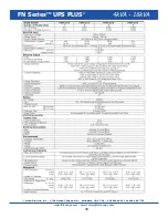
Страница 47: ...FN SeriesTM UPS PLUS 5kVA 20kVA 47...
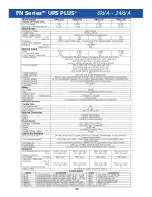
Страница 48: ...48 FN SeriesTM UPS PLUS 6kVA 24kVA...
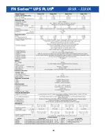
Страница 49: ...49 FN SeriesTM UPS PLUS 8kVA 32kVA...


