background image

9.0 FNB-1S7, FNB-2S7 & FNB-3S7 EXTENDED BATTERY BANK OPTION OVERVIEW

FN Series Extended Battery Bank Option contains: one, two or three 240Vdc parallel strings of 12V, 7AH,
Valve Regulated Lead Acid (VRLA) batteries depending on the model. The FNB-1S7 model adds one 
additional battery string, the FNB-2S7 adds two, and the FNB-3S7 adds three. All strings are in a 
single battery bank enclosure. Multiple enclosures may also be configured. When connected to the FN -2TXI
model UPS, the Extended Battery Bank will provide an extended battery backup time. 

9.1 How to connect the FNB-xS7 or FNB-xS9 extended battery bank to the FN -2TXI Model
UPS.

1. Locate the extended battery installation kit. The kit contains, (1) interface cable, (1) ground cable, (2) 

interface cable connector locking plates and (4) screws.

2. Remove the screws securing the external battery connectors located on the UPS and Extended 

Battery Bank rear panels. (See the picture to the right).

3. Verify the Extended Battery Bank output circuit breaker is in the “Off” position.
4. Connect one end of the extended battery interface cable to the battery connector on 

the UPS rear panel. Secure the connector by sliding the locking plate into the slots on 
the connector and installing the supplied screw.

5. Connect the other end of the extended battery interface cable to the battery connector on the extended 

battery bank rear panel. Secure the connector by sliding the locking plate into the slots on the connector 
and installing the supplied screw.

6. Connect one end of the ground cable to the UPS ground point located on the rear panel and secure with 

the supplied screw. Connect the other end of the ground cable to the grounding point on the battery bank 
rear panel and secure with the supplied screw.

7. Turn on the battery bank output circuit breaker and start up the UPS.
8. Perform a UPS self-test to verify operation.

40

FNB-xS7 or 

FNB-2S9

Extended Battery

Optional fast

recharge battery

chargers are 

available.

Up to (3) additional

chargers may be

added.

Содержание FN10K-2TXI

Страница 1: ...Inc 5116 Azusa Canyon Rd Irwindale California 91706 626 962 7770 Fax 626 962 7720 Email sales falconups com 2011 Falcon Electric Inc All rights reserved All other brand names and trademarks are the pr...

Страница 2: ...ton and LCD Locations 18 5 2 Control Button Operation 18 5 3 LED Display Modes 19 5 4 LCD Display Overview 20 5 5 LCD Icon Descriptions 20 5 6 Status Error Code Descriptions 20 Chapter 6 Operation 6 1...

Страница 3: ...LCD Display with Advanced Monitoring Remote Emergency Power Off REPO Input Power Factor Correction Wide Input Voltage Window Precision Output Voltage Regulation Superior Brownout Surge and Transient...

Страница 4: ...aximum of 104 F 0 C to 40 C This UPS is designed for use with industrial scientific or data processing class equipment WARNING NEVER USE THIS UPS TO POWER LIFE SUPPORT EQUIPMENT OR ANY EQUIPMENT USED...

Страница 5: ...PS circuit breaker acts as the main on off switchs for the UPS It may be turned off to simulate a utility power loss or for performing battery runtime testing The UPS can be completely shutdown when b...

Страница 6: ...of the FN Series units all optional extended battery chargers and any other circuits that may be connected to the panel Please have your electrical contractor review the FN datasheet located at the e...

Страница 7: ...er the UPS is plugged in turned on and operating from utility power The internal UPS battery charger output is rated at 1 9 amps Static Bypass Function NOTE Bypass power will only be available If the...

Страница 8: ...rface Cable 1 UPSilon Software CD 1 Installation Kit 1 Software Interface Cable 1 Owner s Manual NOTE If multiple FN UPS units were received for connection in parallel please verify that one parallel...

Страница 9: ...re the maximum life of the batteries UPS operation in an ambient temperature of 68 F to 77 F 20 C to 25 C is recommended OPERATION IN TEMPERATURES ABOVE 77 F 25 C WILL REDUCE BATTERY LIFE 5 The FN Ser...

Страница 10: ...G 75C copper wire and torque terminal block screws to 17 7 in lb FN5K 2TXI Input Hardwire 208 240Vac 50 60Hz 40A single phase 2 wire plus ground Branch Rated Circuit Breaker Rating 40A Use only 10 AWG...

Страница 11: ...nect circuit breaker must be provided To reduce the risk of fire connect on to a circuit provided with branch rated circuit breaker over current protection Please refer to the table below for the spec...

Страница 12: ...VA 120 V No 2 Output1 0V L1 Output1 120V L2 N 2 5KVA 120 V No 3 Output1 0V L1 Output2 88V L2 5KVA 208 V No 4 Output1 0V L1 Output2 120V L2 5KVA 240 V Use only 10 AWG 75C copper wire and torque termina...

Страница 13: ...4 5 Hardwire Terminal Block Wiring Details FN 2TXI Models Hardwire Terminal Designations Wiring Detail for a 120 240Vac Split Phase Output Wiring Detail for a 120 208Vac Output 13...

Страница 14: ...4 6 Rear Panel Details 14...

Страница 15: ...quency model must not be set if multiple FN units are to be connected in parallel or used in N 1 mode Suggested UPS Output Panel Circuit Breakers UPS Output Panel Square D P NQQ12L125G 1 each Panel Ma...

Страница 16: ...2 Turn on CB1 and CB2 on rear panel and leave the unit in bypass mode BPS 3 Press and hold the ON and Next Page button simultaneously until the unit beeps twice and enters programming mode 4 Using the...

Страница 17: ...g Detail Typical UPS unit with optional FNBC 5A 2 for use with external battery banks only FN6KBC 5A 2 5 Amp External Battery Charger Module FNBC 5A 2 Battery Charger Module Terminal Block Wiring Deta...

Страница 18: ...r battery mode depressing this button will silence any audible alarms Off Bypass Button 1 When the UPS is operating in utility or battery mode depressing and holding this button until an audible beep...

Страница 19: ...n in Programming Mode and prompted on the LCD display to SAVE settings pressing this button will save all changed parameters Utility AC Source 1 UPS Input Power Present LED Green Indicates utility pow...

Страница 20: ...d as part of the MIMIC display In the event of a utility loss that depletes that battery charge the Low Battery icon is displayed until the batteries have recharged to a reasonable level In the event...

Страница 21: ...ng temperature is not too high Verify the UPS cooling fan operation Er12 Error code 12 indicates the UPS output is overloaded similar to error code 10 This could indicate the connected equipment excee...

Страница 22: ...CD display will be shown NOTE Always allow the UPS to charge its batteries for 8 hours prior to use 5 The UPS will now sequence up to on line mode and display the following Display A is an LCD test di...

Страница 23: ...the UPS fails the self test FAIL is displayed alternately with an error code Please note the error code and contact Falcon Service The UPS is now turned on and in on line inverter mode Using an AC vol...

Страница 24: ...tility inverter or battery mode depress the Off button until the UPS sounds two audible beeps The UPS will switch to static bypass and turn off the inverter The LCD will display OFF or BPS The connect...

Страница 25: ...tage Depress the Next Page button The r denotes the reading is for utility The arrow under the LINE indicates the reading is for the utility frequency Depress the Next Page button The b denotes the re...

Страница 26: ...e battery icon indicates the reading is for the battery voltage Depress the Next Page button The degree C symbol indicates the reading is for the internal UPS temperature Depressing the Next Page butt...

Страница 27: ...e alarm buzzer status It is shown here to be turned on If the Previous Page Change Setting button is pressed the audible alarm will be turned off Depressing the button again will turn the alarm back o...

Страница 28: ...n below Depress the Next Page button The next parameter displayed shows acceptable input frequency window The window can be set to 3Hz shown or 1Hz not shown Depress the Next Page button The next para...

Страница 29: ...et to d0 as shown If multiple parallel UPS units are connected in a parallel configuration of up tp 40kVA or up to 30kVA N 1 operation the units would be addressed id01 id02 id03 and id04 See the para...

Страница 30: ...ns at the same time and hold them down until the UPS sounds two beeps The audible alarm status parameter setting will be displayed 30 The audible alarm parameter settings cannot be set in this program...

Страница 31: ...o change the settings depress the Previous Page Change Setting button To change to the alternate setting press the but ton again All setting changes will be saved when prompted at the end of the param...

Страница 32: ...tween these settings depress the Previous Page Change Setting button Repeat pressing the button until the desired mode setting is displayed All setting changes will be saved when prompted at the end o...

Страница 33: ...the UPS is used in a parallel configuration The set tings are P01 and P02 If only one UPS is being configured not paralleled the position should be set to P01 as shown If UPS units are connected in pa...

Страница 34: ...o bypass mode 2 Remove the phillips screw securing the lower side of the maintenance bypass security cover plate 3 Turn the Maintenance Bypass Switch to Bypass The maintenance bypass icon will be disp...

Страница 35: ...CAUTION The internal USHA SNMP HTTP AGENT device must be installed into the Advanced Communications Option Slot specified in this manual Do not attempt to install it in the contact closure option card...

Страница 36: ...isplayed on the LCD panel After removal of the EPO contact closure the UPS must be completely shut down and restarted to clear the EPO condition 7 4 Optional Communications Interface Board Details UA8...

Страница 37: ...8 9 10 Pin 1 UPS on Bypass N O Pin 2 Utility Abnormal N O Pin 3 Utility Normal N C Pin 4 Inverter On N C Pin 5 Low Battery N O Pin 6 Abnormal Battery N O Pin 7 UPS Summary Alarm N O Pin 8 Common Pin...

Страница 38: ...t least 24 hours every four to six months to ensure full recharging of the batteries This will prevent excessive battery self discharge 3 When to Replace Batteries We suggest the battery pack s be rep...

Страница 39: ...ront of the unit 6 Unpack the new battery packs Take care not to destroy the packaging Compare the new and old battery packs and verify that they are the same type If so proceed with the next step oth...

Страница 40: ...panels See the picture to the right 3 Verify the Extended Battery Bank output circuit breaker is in the Off position 4 Connect one end of the extended battery interface cable to the battery connector...

Страница 41: ...ors located on the UPS rear panel that supports interconnection of the paralleled UPS units 1 parallel UPS interface kit must be purchased from Falcon for each UPS to be paralleled The interface kit c...

Страница 42: ...tches rings and other metal objects Use tools with insulated handles Do not lay tools or metal parts on top of batteries Do not attempt to alter any battery wiring or connectors Attempting to alter wi...

Страница 43: ...se the original shipping container and packing materials will likely result in the unit being received by Falcon with shipping damage Falcon Electric will not assume any responsibility for shipping da...

Страница 44: ...de of Falcon s control such as fire accidents impacts iv normal wear and tear such as cleaning and replacement of batteries The warranty is null and void if i the product is used in conjunction with l...

Страница 45: ...45 Falcon Electric Inc 5106 Azusa Canyon Rd Irwindale CA 91706 800 842 6940 Fax 626 962 7720 www falconups com email sales falconups com FN SeriesTM UPS PLUS 3kVA 12kVA...

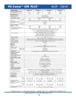
Страница 46: ...46 Falcon Electric Inc 5106 Azusa Canyon Rd Irwindale CA 91706 800 842 6940 Fax 626 962 7720 www falconups com email sales falconups com FN SeriesTM UPS PLUS 4kVA 16kVA...

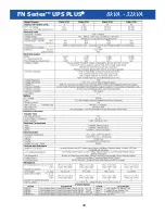
Страница 47: ...FN SeriesTM UPS PLUS 5kVA 20kVA 47...

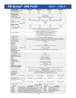
Страница 48: ...48 FN SeriesTM UPS PLUS 6kVA 24kVA...

Страница 49: ...49 FN SeriesTM UPS PLUS 8kVA 32kVA...

Страница 50: ...50 FN SeriesTM UPS PLUS 10kVA 40kVA Falcon Electric Inc 5106 Azusa Canyon Rd Irwindale CA 91706 800 842 6940 Fax 626 962 7720 www falconups com...

Отзывы: