Description
GSM–modem
A2D–JP
Version 1.03
Side 16
5.1.4 SIM card reader
Internal, for small SIM cards (3 V)
External, 10
…
15 cm maximum cable length
5.1.5 RS 232
5.1.6 Possible external devices
5.2
Special functionality pins
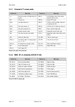
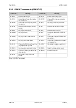
Table 6 and Tabl e7 show the pin-configuration of the AMP
177984-2.
In these tables CMOS means 2.8 V. You may use a 3 V or 3.3 V
CMOS level logic (never 5 V) on the 2.8 V I/O's. However, it is requi-
red to add serial resistance on all the lines you will use (typical value:
from 4.7 to 10 K
Ω
).
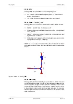
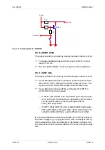
There are a few pins needed for the operation of the module. The
handling of that pins is described as follows.
RS 232
2.8 V
RX, TX, RTS, CTS, DTR, DSR, DCD, RI
300..115200
Baud rates for serial link (2400
…
19200 with auto-bauding)
Table 10: RS 232
Audio
2 K
Ω
Ω
Ω
Ω
differential
Microphone 1 impedance
2 V
Microphone 1 bias voltage
0,5 mA
Microphone 1 input current
2 K
Ω
Ω
Ω
Ω
differential
Microphone 2 impedance
2 V
Microphone 2 bias voltage
0,5 mA
Microphone 2 input current
> 50
Ω
Ω
Ω
Ω
(<1nF)
Speaker 1 impedance
> 50
Ω
Ω
Ω
Ω
(<1nF)
Speaker 2 impedance
Table 11: Audio
Содержание A2D-JP
Страница 1: ...Description Embedded GSM GPS Module A2D JP...

