8
bar
0
20
40
60
80
100
120
0
1
4
2
3
317
=
=
3
2
1
4
5
98
56
56
98
25
100
800
440
=
=
156
60
111
36
111
5
6
4
3
2
1
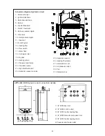
1. 1/2” BPS Gas inlet
2. 1/2” BPS D.H.W. outlet
3. 3/4” BPS Central heating flow
4. 1/2” BPS Domestic cold water inlet
5. 3/4” BPS Central heating return
6. Pressure relief valve outlet
Schematic diagram- Hydraulic circuit
1.- Heat exchanger
2.- Ignition
Electrode
3.-
Detection electrode
5.- Burner
6.- Injector Manifold
7.- D.H.W Thermistor
8.-
Burner
pressure nipple
9.- Gas valve
10.- Inlet pressure nipple
11.- Gas inlet
13. D.H.W outlet
14.- Heating flow
16.- Flow switch
17.- Water filter
18.- Cold water inlet
19.- By-pass
20.- Heating return
21.- Pressure relief valve
22.- Circulation pump
23.-
High limit
thermostat
24.- Expansion vessel
air valve
25.- Expansion vessel
26.- Heating Thermistor
27.- Automatic air vent
29.- Air pressure switch
30.- Fan
31.-
S
ealed
air box
27
1
2
3
5
6
7
8
9
10
11
13
14
16
17
18
19
20
21
22
23
24
25
26
29
30
31
APPLIANCE Dimensions and connection details
Содержание FEB-20E UK ECOPLUS
Страница 1: ...FEB 20E UK ECOPLUS USER INSTRUCTIONS AND TECHNICAL INSTRUCTIONS...
Страница 23: ......


