


15
Rangehood Control Panel
The control panel is located in the center of the
hood bottom.
Light On/Off Button (A)
On/Off switch for the lights. Position "0" turns the
lights Off, turning the switch to the right is On.
Blower On/Off Button (B)
On/Off switch for the blower. Move the dial to the
right to turn the blower ON and vary the speed of
the blower. Turn to the left at "0" to turn it OFF.
For Best Result
Start the rangehood several minutes before
cooking to develop proper airflow. Allow the unit
to operate for several minutes after cooking is
complete to clear all smoke and odors from the
kitchen.
Cleaning
The stainless steel grease filters and grease rail
should be cleaned frequently in hot detergent
solution or washed in the dishwasher. Clean
exterior surfaces with a commercially available
stainless steel cleaner. Abrasives and scouring
agents can scratch stainless steel finishes and
should not be used to clean finished surfaces.
Grease rail and Grease Filter Installation /
Removal.
Remove the plastic from the filter, the knobs
need to be installed onto the filter with 2
screws to each filter.
Version 07/11 - Page 11
Light On/Off Button (A)
On/Off switch for the halogen lights. Position "0" turns the lights off,
turning the switch to the right one click is the dimmer position, and
the next click to the right is full power
Blower On/Off Button (B)
On/Off switch for the blower. Move the dial to the right to turn the
blower ON and vary the speed of the blower. Turn to the left at "0"
to turn it OFF.
For Best Result
Start the rangehood several minutes before cooking to develop proper
airflow. Allow the unit to operate for several minutes after cooking is
complete to clear all smoke and odors from the kitchen.
Cleaning
The stainless steel grease filters and grease rail should be cleaned
frequently in hot detergent solution or washed in the dishwasher.
Clean exterior surfaces with a commercially available stainless steel
cleaner. Abrasives and scouring agents can scratch stainless steel
finishes and should not be used to clean finished surfaces.
Grease rail and Grease Filter Installation / Removal
Remove the plastic from the filter, the knobs need to be installed
onto the filter with 2 screws to each filter
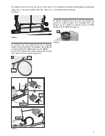
Install the grease rail into the back of the hood, into the slots on the
inside floor of the rear of the hood. The Grease filters should be
installed before operating the rangehood. To install the filters, use the
two knobs (in FIGURE 28) to hold the filter and insert the filter into
the front edge of the hood with the knobs facing out into the spring
loaded slot. Install the other end of the filter above the grease rail in
the back of the hood.
USE AND CARE INFORMATION
This rangehood system is designed to remove smoke, cooking vapors
and odors from the cooktop area.
Rangehood Control Panel
The control panel is located in the center of the hood bottom. The
position and function of each control button are indicated in
FIGURE
27
FIGURE 28
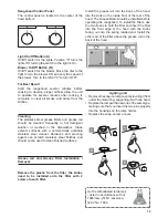
Replacing the Halogen Lamp
Before you begin, make sure that the rangehood is turned off and
that the other lamps have had sufficient time to cool. Halogen lamps
burn extremely hot and serious injury could result from touching a hot
lamp. Press and twist the lamp to remove. Then remove the lamp
and replace with a new lamp.
WIRING DIAGRAM
This rangehood uses 45 watt PAR16
Halogen Lamps.
FIGURE 27
FIGURE 26
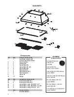
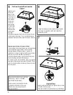
ALL INSTALLATIONS
1. Use a drill to install side rails on the inside rangehood walls to
line the inside hood wall with stainless, 2 and 3 in FIGURE 26 with
9a. screws, 4 screws total.
BLK
WHT
R11B41
LIGHT CONTROL
OFF / HALF LIGHT / ON
1
Y-G
A
RED
WIRING BOX
WHT
BLK
BLK
2
3
B
ORG
WHT
4
VLT
N
L
Y-G
LINE IN
120Vac
60Hz ~
Y-G
BL
U
1
2
3
6
5
4
7
8
9
1
2
3
6
5
4
9
8
7
RED
M8 4V
120V ~
WHT
BRW
BL
U
BL
K
O
RG
BLU BLK
Y-G
Y-G
ON/OFF MOTOR
SPEED CONTROL
BLK
BLK
BL
U
1
2
3
6 5
4
7
8
9
1 2
3
6
5
4
9
8
7
RED
M8 4V
120V ~
BLU
Y-G
WHT
BRW
BLK
BLK
BL
U
1
2
3
6
5
4
1
2
3
6
5
4
BL
K
O
RG
Y-G
BLU
WHT
BLK
Y-G
WIRING BOX FOR
REMOTE BLOWER
WHT
REMOTE
BLOWER
1
2
3
6
5
4
WHT
Y-G
BLK
BLK
Y-G
9a
9a
2
3
9a
9a
Gu10 self-ballasted led lamps
– listed in accordance with ul
1993/nmx-j-578/1-ance/csa
c22.2 No. 1993
Lighting unit
• Remove the snap-on lamp cover by levering it from
under the metal ring, supporting it with one hand.
• Replace the lamp with a new one of the same type,
making sure that you insert the two pins properly
into the housings on the lamp holder.
• Replace the snap-on lamp cover.
a
b
a
b
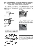
Install the grease rail into the back of the hood,
into the slots on the inside floor of the rear of the
hood. The Grease filters should be installed before
operating the rangehood. To install the filters, use
the two knobs to hold the filter and insert the filter
into the front edge of the hood with the knobs
facing out into the spring loaded slot. Install the
other end of the filter above the grease rail in the
back of the hood.
A
B
Содержание INCA PRO PLUS
Страница 16: ...16 Wiring Diagram...
Страница 32: ...32 Sch ma de c blage...
Страница 34: ......
Страница 35: ......
Страница 36: ...991 0463 718_01 170516 D003712_00...


