


11
5
5
4
4
9c
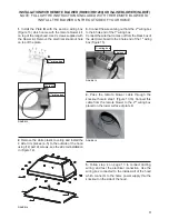
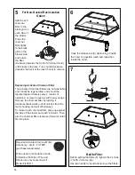
INSTALLATION WITH REMOTE BLOWER (RB900 / RB1200) OR IN-LINE BLOWER (INLBKIT)
NOTE: FOLLOW THE INSTRUCTIONS INCLUDED WITH THE REMOTE BLOWER TO
INSTALL THE BLOWER ON THE OUTSIDE OF YOUR HOME.
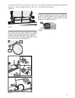
1.
Install the Plate
B
with the second wiring box
(Figure 13) which came with the remote blower kit,
on top of the rangehood. Use 9 screws supplied with
the blower kit. Remove the electrical knockout hole
on top of the plate.
2.
Remove the white plastic covering and Install the
4 side trim pieces (4-5) to the outside of the hood
using (14) part 9c screws, see the side rail installation
in (Figure 14).
FIGURE 14
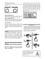
3.
Connect the wire coming out from the 2
nd
wiring box
to the 6 hole end of the 1
st
wiring box.
Connect the wire that comes out from the black box of
the electronic board to the 9 hole end of the 1
st
wiring
box (Figure 15).
Version 07/11 - Page 10
INSTALLATION WITH REMOTE BLOWER (RB900 / RB1200)
OR IN-LINE BLOWER (INLBKIT)
NOTE: FOLLOW THE INSTRUCTIONS INCLUDED WITH THE
REMOTE BLOWER TO INSTALL THE BLOWER ON THE
OUTSIDE OF YOUR HOME
.
1.
Install the Plate B (FIGURE 21) which came with the remote
blower kit, on top of the rangehood. Use 9 screws supplied with
the blower kit. Remove the electrical knockout hole on top of the
plate.
2.
Remove the white plastic covering and Install the 4 side trim
pieces to the outside of the hood using (16) part 9b screws, see
the side rail installation in (FIGURE 22).
FIGURE 23
FIGURE 24
4. Feed the remote blower cable thru the knockout hole in step 1
(FIGURE 24). Connect the power supply cable from the remote
blower to the wiring box on the top ducting plate of the hood. Use
step 6 on page 8 and the diagram on page 8 (FIGURE 13)
5.
Attach the hood to the cabinet using (12) 9c. screws to the
cabinet. FIGURE 25
6. Follow steps 6 - 9 on page 8 to connect ducting, wiring, and
test the electrical connection. Use the wiring box connected to
the inside wall of the hood which connects to the home power
supply thru the knockout on the side of the hood.
FIGURE 21
FIGURE 22
3.
Connect the wire coming out of the wiring box on the top duct
plate to the light panel 6 hole slot connector on the front inside
of the hood (FIGURE 23)
FIGURE 25
B
4.
Pass the remote blower cable through the
knockout hole in step 1 (Figure 13,16). Connect this
cable from the remote blower to the 2
nd
wiring box
placed on the lower surface of plate B.
5.
Follow step 4 on page 13 to connect ducting,
wiring, and test the electrical connection. Use the
wiring box connected to the inside wall of the hood
which connects to the home power supply thru the
knockout on the side of the hood.
FIGURE 16
Version 07/11 - Page 10
INSTALLATION WITH REMOTE BLOWER (RB900 / RB1200)
OR IN-LINE BLOWER (INLBKIT)
NOTE: FOLLOW THE INSTRUCTIONS INCLUDED WITH THE
REMOTE BLOWER TO INSTALL THE BLOWER ON THE
OUTSIDE OF YOUR HOME
.
1.
Install the Plate B (FIGURE 21) which came with the remote
blower kit, on top of the rangehood. Use 9 screws supplied with
the blower kit. Remove the electrical knockout hole on top of the
plate.
2.
Remove the white plastic covering and Install the 4 side trim
pieces to the outside of the hood using (16) part 9b screws, see
the side rail installation in (FIGURE 22).
FIGURE 23
FIGURE 24
4. Feed the remote blower cable thru the knockout hole in step 1
(FIGURE 24). Connect the power supply cable from the remote
blower to the wiring box on the top ducting plate of the hood. Use
step 6 on page 8 and the diagram on page 8 (FIGURE 13)
5.
Attach the hood to the cabinet using (12) 9c. screws to the
cabinet. FIGURE 25
6. Follow steps 6 - 9 on page 8 to connect ducting, wiring, and
test the electrical connection. Use the wiring box connected to
the inside wall of the hood which connects to the home power
supply thru the knockout on the side of the hood.
FIGURE 21
FIGURE 22
3.
Connect the wire coming out of the wiring box on the top duct
plate to the light panel 6 hole slot connector on the front inside
of the hood (FIGURE 23)
FIGURE 25
B
FIGURE 13
2
nd
wiring box
2
nd
wiring box
6 hole end
FIGURE 15
1
st
wiring box
6 hole end
Содержание INCA PRO PLUS
Страница 16: ...16 Wiring Diagram...
Страница 32: ...32 Sch ma de c blage...
Страница 34: ......
Страница 35: ......
Страница 36: ...991 0463 718_01 170516 D003712_00...


