Faber Dama Isola Скачать руководство пользователя страница 9

Version 08/10 - Page 9
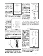
FIGURE 16

FIGURE 17

USE  AND  CARE  INFORMATION

This rangehood system is designed to remove smoke, cooking 

vapors and odors from the cooktop area.

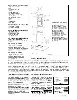
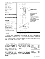
Rangehood Control Panel

The control panel is located on the front edge of the rangehood 

canopy.  The position and function of each control button are 

indicated in 

FIGURE 16

.

Light On/Off Button ( L )

On/Off switch for the halogen  lights.    Push the button in to turn 

the light ON, push again to turn the light OFF.

Blower 

Indicator Light  ( I )

Lights up to indicate blower is ON.

Blower 

On/Off and Speed Buttons ( 1, 2, 3 )

Push button (1) to turn ON and OFF the blower.  This button 

must  be  pushed  in  for  the  blower  to  operate  regardless  of 

speed chosen.  Button (1) operates the blower on LOW speed.  

Push button (2) for MEDIUM speed.  Push button (3) for HIGH 

speed.

For Best Results

Start the rangehood several minutes before cooking to develop 

proper airflow.  Allow the unit to operate for several minutes 

after cooking is complete to clear all smoke and odors from 

the kitchen.

Cleaning

The stainless steel grease filters should be cleaned frequently in 

hot detergent solution or washed in the dishwasher.   Stainless 

steel cleaner should be used on stainless rangehoods.  Abrasives 

and scouring agents can scratch stainless steel finishes and 

should not be used to clean finished surfaces.
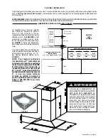
Replacing the Lamps

Before attempting to replace the lamps, make sure that the 

light switch is turned off.  Remove the 2 screws 

(as indicated 

in FIGURE 17)

 that hold the light support and gently pull the 

support down from the hood.  Remove the lamp from the light 

support and replace with new lamp.  Replace the light support 

and fix it into place with the 2 screws. 

An alternative method to replace the lamps is to use a 1 1/4" 

suction cup (

FIGURE 18

). Attach the suction cup to the bulb 

and pull firmly down on the bulb and replace with a new lamp. 

• This rangehood uses 20 watt halogen lamps.

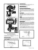
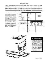
WIRING  DIAGRAM (600 CFM)

FIGURE 18

WIRING  DIAGRAM (280 CFM)

Содержание Dama Isola

Страница 1: ...ejamaislaisser un élément de la table de cuisson fonctionner sans surveillance à la puissance de chauffage maximale un renversement débordement de matière graisseuse pourrait provoquer une inflammation et le génération de fumée Utiliser toujours une puissance de chauffage moyenne ou basse pour le chauffage d huile b Veiller à toujours faire fonctionner le ventilateur de la hotte lors d une cuisson...

Страница 2: ...ut a 1 1 4 hole in the wall A hole cut through wood must be sanded until smooth A hole through metal must have a grommet WARNING TO REDUCE THE RISK OF FIRE OR ELECTRIC SHOCK do not use this fan with any solid state speed control device WARNING TO REDUCE THE RISK OF FIRE ELECTRI CAL SHOCK OR INJURY TO PERSONS OBSERVE THE FOLLOWING Use this unit only in the manner intended by the manufacturer If you...

Страница 3: ...ritédufournisseurtelsqueceuxpubliés par l Association Nationale de la Sauvegarde contre l Incendie et l Association Américaine d Ingénieurs de Chauffage Frigorifaction et Air Climatisé ainsi que les codes municipaux En perçant un mur veillez à ne pas perforer un autre fil électrique Une ventilateur à évacuation extérieure doit être raccordée à l extérieur AVERTISSEMENT Le système d évacuation DOIT...

Страница 4: ...crews on the outside bottom of the chimney cover Remove the UPPER CHIMNEY COVER C from the CHIMNEY SUPPORT F by removing the 2 philips screws on the outside top of the chimney cover CALCULATE THE DUCTRUN LENGTH The ductrun should not exceed 35 equivalent feet if ducted with the required minimum of 6 roundduct Calculatethelengthoftheductwork by adding the equivalent feet in FIGURE 2 for each piece ...

Страница 5: ... section of the support structure FIGURE 5 needs to be removed Out of the box the minimum chimney length is 32 not27 asshowninthedimensional diagram Add 5 to all minimum ceiling heightcalculations ifkeepingthemiddle section in place Contact Faber at 508 358 5353 for more information DUCTED INSTALLATION DIMENSIONS vented to the outside PLAN THE INSTALLATION This rangehood can be installed as either...

Страница 6: ...udes an additional support structure which adds 27 1 2 to the various ceiling heights in FIGURE 6 upper chimney cover ductless lower chimney cover canopy cabinet base x distancefromhoodtocooktop varies depending on installation min 24 suggested max 30 also consult cooktop manufacturer s recommendation 8 3 8 min 15 3 8 max 23 5 8 36 FIGURE 6 DUCTLESS DIMENSIONS x min max ceiling height examples x 3...

Страница 7: ...OVER C in FIGURE 11 attaches using two screws provided GinFIGURE11 If using the High Ceiling Chimney Kit use the UPPERCHIMNEYCOVER supplied with the kit Slide up and attach the UPPER CHIMNEY COVER 2 Attachtheductworktothe DAMPER MinFIGURE1 Make sure to seal all joints with duct tape to prevent leaks 3 The LOWER CHIMNEY COVER B in FIGURE 11 attaches using two screws provided G in FIGURE 11 Install ...

Страница 8: ...IGURE 12 FIGURE 14 6 Install the grease filters FIGURE 15 FIGURE 15 7 Turn the power supply on Turn on blower and lights If the rangehood does not operate check that the circuit breaker is not tripped or the house fuse blown If the unit still does not operate disconnect the power supply and check that the wiring connections have been made properly 5 Connect the CONTROL CABLES together as indicated...

Страница 9: ...develop proper airflow Allow the unit to operate for several minutes after cooking is complete to clear all smoke and odors from the kitchen Cleaning Thestainlesssteelgreasefiltersshouldbecleanedfrequentlyin hot detergent solution or washed in the dishwasher Stainless steelcleanershouldbeusedonstainlessrangehoods Abrasives and scouring agents can scratch stainless steel finishes and should not be ...

Страница 10: ...lumbing 2 Service calls to repair or replace range hood light bulbs fuses or filters Those consumable parts are excluded from warranty coverage 3 Repairs when your range hood is used for other than normal single family household use 4 Damage resulting from accident alteration misuse abuse fire flood acts of God improper installation installation not in accordance with electrical or plumbing codes ...

Страница 11: ...ONGUEUR DU CONDUIT La longueur du conduit ne doit jamais excéder 35pis ils agitdeconduitrondde6po Calculer la longueur du conduit en ajoutant l équivalent en pied de la figure 2 pour chaque pièce du conduit du système Un exemple est donné à la figure 3 Pour de meilleurs résultats ne pas utiliser plus de trois coudes de 90o S assurer qu il y ait un minimum de 24 po de conduit droit entre les coudes...

Страница 12: ...9 pi 1 3 4 po regardez la distance entre la hotte et la table de cuisson X en FIGURE 4 Cela s accomplit en utilisant plus ou moins du couvercle de la cheminé supérieure La FIGURE 4 illustre les dimensions de chaque pièce du modèle Diamante Isola Pour des installations plus élevées de plafondinclutunestructredesoutènemant additionnelle qui additionne 27 1 2 aux diverses tailled de plafond sur le FI...

Страница 13: ...3 4 po x 24 po min 8 pi 3 4 po max 8 pi 7 3 4 po dimensions d installatioN SANS CONDUIT 121 2 po 4 3 4 po 3 1 2 po à cause de la dimension et du poids de cette hotte le support doit Être fixé fermement au plafond Pour les plafonds en plâtre ou en panneaux muraux secs le support doit être fixé aux solives Si cela est impossible une structure renforcée doit être érigée derrière le plâtre ou les pann...

Страница 14: ... Déterminer et marquer clairement à l aide d un crayon la ligne centrale sur le mur où la hotte sera installée 3 Un gabarit Lde la FIGURE 7 pour installer le support est fourni aveccedernier Utilisercegabarit pourmarquerlestrousdusupport au plafond INSTALLATIONS SANS CONDUIT 1 Le COUVERCLE CHEMINÉE SUPÉRIEURE C de la FIGURE 11 se fixe avec les deux vis fournies G de la FIGURE 11 Si en utilisant Le...

Страница 15: ...ircuit Mettreencircuitleventilateur et la lumière Les interrupteurs de contrôle de la hotte se trouvent à droite sous la hotte Si la hotte ne fonctionne pas vérifiersiledisjoncteurn estpasdéclenchéousilefusiblen est pas grillé Si l appareil ne fonctionne toujours pas débrancher l alimentation et vérifier si les connexions ont été effectuées correctement 5 Connecter le CONNECTEUR DES COMMANDES A de...

Страница 16: ... l acier inoxydable sur les hottes en acier inoxydable Ne pas utiliser de produits abrasifs ou de récurants car ils peuvent égratigner le fini en acier inoxydable et ils ne devraient pas être employés pour nettoyer les surfaces de finition Remplacement de la lumière halogène Avant d essayer de remplacer les ampoules s assurer que l interrupteur soit hors circuit Retirer les deux vis de la FIGURE17...

Страница 17: ... les fusibles de votre maison ou pour corriger votre câblage ou votre système de plomberie 2 Les appels de service pour remplacer ou réparer les ampoules les fusibles ou les filtres de votre hotte de cuisinière 3 Les réparations lorsque votre hotte de cuisinière a été utilisée plus que la normale c est à dire plus que pour une famille par foyer 4 Les dommages résultant d un accident de l altératio...

Отзывы: