background image


L   

7 < 

<


<


<


3


Installation requirements 

3.1


The fire  


The appliance must be built into an existing or a newly to be constructed false 

chimney breast. 


In appliances with flexible gas pipes, the gas control valve is mounted to the right 

side of the fire for safe transport . Unscrew it and mount it at a distance of max. 30  

cm behind the access door. 


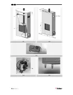
The receiver which has been attached in a transport holder (see fig. 1.4 A) to the 

side of control valve bracket, can now be slid onto the top of the control valve 

bracket. The transport holder can be removed now. 

3.2


False Chimney breast 


The false chimney breast must be constructed of an non-combustible material. 


Always ventilate the space above the appliance by means of the grills or a 

comparable alternative with a minimum air supply of 200 cm². 


For the finish, use special stucco (min. 100°C resistant) or glass fibre wallpaper to 

prevent discoloration or cracks etc. Recommended drying time: for plaster is a 

minimum of 24 hours per mm of coat applied. 


The false chimney breast and its construction may not rest on the appliance  


3.3


 Requirements flue system and outlets 


You should always make use of the materials prescribed by Faber International Ltd. 

Only by using these materials can Faber International Ltd. guarantee a proper 

functioning. 


The outside of the concentric flue material can reach a temperature of  

Approx 150°C. Make sure of proper isulation and protection in case of transit 

through combustible wall or ceiling constructions. And observe sufficient distance. 


Make sure that the concentric flue materials are bracketed every 2 metres when 

they have an extended length, so that the weight of the flue material is not resting 

on the appliance  itself. 


You may never start with a cut-down concentric pipe directly on to the appliance. 


Содержание Clear

Страница 1: ...Clear 40010631 0938 Installation guide ENG ENG ...

Страница 2: ...L 1 1 1 1 2 1 3 1 4 1 5 A ...

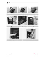
Страница 3: ...L 2 A B 2 1 2 2 2 3 2 4 2 5 C ...

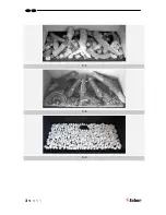
Страница 4: ...L 3 3 1 3 2 3 3 ...

Страница 5: ...chimney breast 10 4 7 False Chimney breast 10 4 8 Frameless 10 4 9 surround 10 5 removing the glass 11 6 Placing the decorative material 11 6 1 Imitation logs Flatburner 11 6 2 Imitation logs Logburner 12 6 3 Pebbles 12 7 Checking the installation 12 7 1 Checking the ignition of the pilot burner main burner 12 7 2 Checking for gas leakage 12 7 3 Checking the burner pressure and the pre pressure 13...

Страница 6: ...ns 16 12 Table 17 12 1 Table Flatburner 17 12 2 Table logburner 18 13 Technical data 19 13 1 Flatburner 19 13 2 Logburner 20 14 Dimension of the appliance 21 15 Dimension of the surround Wirdum 770 22 16 Dimension Ventilation Grills 23 17 Dimension Service Hatch 24 ...

Страница 7: ...or ambience and heating purposes This means that all surfaces of the appliance including the glass can become very hot hotter than 100 C An exception to this are the bottom of the appliance and the controls Do not place any inflammable materials within a of 0 5 m of the radiation of the appliance and ventilation grills Due to natural air circulation of the appliance moisture and volatile component...

Страница 8: ...the finish use special stucco min 100 C resistant or glass fibre wallpaper to prevent discoloration or cracks etc Recommended drying time for plaster is a minimum of 24 hours per mm of coat applied The false chimney breast and its construction may not rest on the appliance 3 3 Requirements flue system and outlets You should always make use of the materials prescribed by Faber International Ltd Onl...

Страница 9: ...existing chimney The existing chimney will function as an air supply and a flexible stainless steel pipe drawn up through the chimney will remove the combustion gas The flexible stainless steel pipe of Ø 100 mm should have a CE mark for temperatures up to 600 Celsius The chimney should comply with the following requirements The diameter of the flue system must be at least 150x150 mm There should b...

Страница 10: ...ourhood of the hearth 4 3 Preparation of the appliance Remove the packaging of the appliance Make sure the gas pipes underneath the appliance are not damaged Clear a safe space to store the frame and the glass Remove the frame if necessary and the glass and take the separately wrapped parts out of the appliance Prepare the gas connection to the gas control valve 4 4 Placing the appliance Take the ...

Страница 11: ...pliance as described in chapter 7 checking the installation 4 7 False Chimney breast Construct the false chimney breast from non combustible material in combination with metal profiles or of brickwork aerated concrete bricks Take the grills and the service panel into account see fig 1 1 and 1 2 Place a protective shield made of non inflammable material above the grills see fig 1 1 A Always use a l...

Страница 12: ...ent or more materials to the combustion chamber Always keep the pilot burner free from decorative material Do not toss all the decorative material onto the burner all at once it can be obstructed by dust particles 6 1 Imitation logs Flatburner Place a number of the chips onto the burner and on the cover plate Place the imitation logs according to instructions see fig 3 1 or imitation logs instruct...

Страница 13: ...plied Avoid a double layer this has a negative effect on the fire image Place the glass and check the fire image 7 Checking the installation 7 1 Checking the ignition of the pilot burner main burner Start the pilot and main burner according to the instructions in the user s manual Check whether the pilot light is properly positioned above the main burner and is not covered by chips an imitation lo...

Страница 14: ... see fig 1 3 a few turns and connect a pressure gauge hose to the gas control valve The pressure must agree with the value indicated on the registration plate In case of deviations get in touch with the manufacturer Close the pressure gauge nipples and check these for gas leaks 7 4 Checking the flame picture Allow the applaince to burn for at least 20 minutes at full and then check the flame pictu...

Страница 15: ...gs instruction card o Suction lifters 9 Annual maintenance 9 1 Service and cleaning Check and clean if necessary after checking o The pilot light o The burner in an LPG flat burner replace the burner sheet o The combustion chamber o The glass o The logs for possible fractures o The outlet 9 2 Replace o in an LPG flat burner replace the burner sheet o If necessary the chips embers 9 3 Cleaning the ...

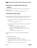
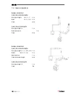
Страница 16: ...rminal always counts as 1 metre To define the horizontal length all lengths of flue pipes in a horizontal direction should be added up every 90 bend in the horizontal part counts as 2 metres every 45 bend in the horizontal part counts as 1 metre Turns from vertical to horizontal or vice versa are not reckoned in the calculation The wall terminal always counts as 1 metre If there is transit under 4...

Страница 17: ...d D 1 x 2 m 2 m Total 4 m Count the vertical lengths Flue pipe length A 1 m Roof terminal G 1 m Total 2 m Sample calculation 2 Count the horizontal lengths Flue pipe lengths J L 0 5 0 5 1 m Bends K M 2 2 m 4 m Wall terminal 1 m Total horizontal length 6 m Count the vertical lengths Flue pipe length H 1 m Total 1m ...

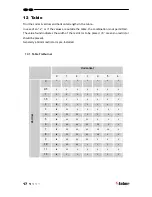
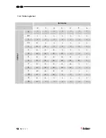
Страница 18: ...aced 0 means no restrictor should be placed Generally a 30mm restrictor is pre installed 12 1 Table Flatburner Horizontal 0 1 2 3 4 5 6 0 X X X X X X X 0 5 X X X X X X X 1 0 0 0 X X X X 1 5 0 0 0 0 X X X 2 30 0 0 0 0 X X 3 30 30 0 0 0 0 X 4 40 30 30 0 0 0 X 5 40 40 30 30 0 0 X 6 50 40 40 30 30 0 X 7 50 50 40 40 30 30 X 8 60 50 50 40 40 X X 9 60 60 50 50 X X X 10 65 60 60 X X X X 11 65 65 X X X X X...

Страница 19: ...0 X X X X X 1 0 0 0 0 X X X 1 5 30 0 0 0 0 X X 2 30 30 0 0 0 0 0 3 40 30 30 0 0 0 0 4 40 40 30 30 0 0 0 5 50 40 40 30 30 0 0 6 50 50 40 40 30 30 0 7 50 50 50 40 40 X X 8 60 50 50 50 40 X X 9 605 60 50 50 X X X 10 65 60 60 X X X X 11 65 65 X X X X X Vertical 12 65 X X X X X X ...

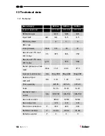
Страница 20: ...925 266 350 Gas rate at 15ºC and 1013 mbar gr h 670 660 Burner pressure at full mark mbar 11 0 22 0 27 5 Injector main burner mm Bray 900 Bray 280 Bray 280 Reduced input restraint mm 2 10 1 30 1 30 Pilot assembly SIT145 SIT145 SIT145 Code Nr 36 Nr 23 Nr 23 Diameter inlet outlet mm 100 150 100 150 100 150 Gas control valve GV60 GV60 GV60 Gas connection 3 8 3 8 3 8 Electrical connection V 220 220 22...

Страница 21: ...228 293 Gas rate at 15ºC and 1013 mbar gr h 580 550 Burner pressure at full mark mbar 11 5 23 5 29 0 Injector main burner mm 3x1 50 3x0 90 3x0 90 Reduced input restraint mm 1 8 1 1 1 1 Pilot assembly SIT160 SIT160 SIT160 Code Nr 51 Nr 30 Nr 30 Diameter inlet outlet mm 100 150 100 150 100 150 Gas control valve Gv60 Gv60 Gv60 Gas connection 3 8 3 8 3 8 Electrical connection V 220 220 220 Batteries r...

Страница 22: ...L 21 14 Dimension of the appliance ...

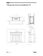
Страница 23: ...L 22 15 Dimension of the surround Wirdum 770 ...

Страница 24: ...L 23 16 Dimension Ventilation Grills ...

Страница 25: ...L 24 17 Dimension Service Hatch ...

Страница 26: ...L 25 ...

Страница 27: ...26 L ...

Страница 28: ...www faber nl info faber nl Saturnus 8 NL 8448 CC Heerenveen Postbus 219 NL 8440 AE Heerenveen T 31 0 513 656500 F 31 0 513 656501 ...

Отзывы: