


Ø 10,5 mm
=
=
ENGLISH
4
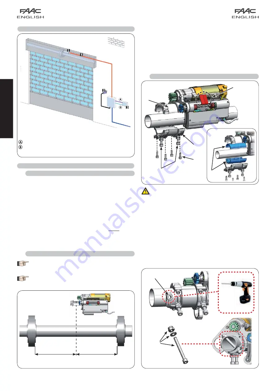
3 INSTALLING THE AUTOMATED SYSTEM
2 ELECTRIC
PREPARATIONS
(standard system)
3.1 PRELIMINARY
CHECKS
To ensure a correctly operating automated system, the structure
of the existing shutter or shutter to be built must satisfy the following
requirements:
• Dimensions and maximum weight as per specifications in Tab. 1.
• Strong, well constructed shutter structure.
• Smooth rise and descent movement, free of any irregular friction along
its entire travel.
• The rotation pins and moving parts must be in good condition.
• Shutter well balanced during its entire travel.
We advise you to carry out the metalwork jobs if any, before installing
the application.
The condition of the structure directly influences the reliability and safety
of the automated system.
3.2 INSTALLATION
DIMENSIONS
3.3 INSTALLING THE OPERATOR
Drive unit FAAC R180 / R280
Key operated switch
Electronic control board
Optional electro-brake
Low voltage cable No.1= 3 x 0,5 mm
High voltage cables No.1 2 x 1,5 mm
2
+ earth
and No. 1 3 x 1,5 mm
2
+ earth
Fig. 4
Fig. 6
Fig. 5
Before taking the necessary measurements, accura-
tely clean the shutter shaft removing deposits of dust,
grease and chips, …
To install two R180 or R280 operators on a shutter
having a width of over 4.5 meters, please refer to
chapter 8 on page 8.
Procedure for defining the correct position of the operator:
Fully unwind the shutter to obtain access to the winding shaft;
As shown in Fig. 5, find the mid-point of the winding shaft and mark
it for subsequent use;
Install the operator, following the instructions in chapter 3.3,
positioning the electric motor on the right of the shaft as shown in
Fig. 5.
1.
2.
3.
During the installation operations, take great care NOT TO
REMOVE the service bracket, ref.
Fig.6, in order not to
compromise the initial position of the travel-limit devices.
Install the operator as follows:
Position the operator body on the shaft, with the central part of
the securing flange (ref.
of Fig.6) on the mid-point previously
measured in chapter 3.2;
If winding shafts with a diameter of 48 or 42 mm (previously
measured in chapter 1.2) are being used, fit the supplied reductions
as shown in Fig. 6A ref.
;
Close the securing flange with its counterpart in ref.b, using the four
screws in ref.
;
Tighten CAREFULLY the operator on the winding shaft, using the
two pressure screws and relevant lock-nuts in ref.
, reducing the
cupling spaces;
1.
2.
3.
4.
Fig. 7
Fig. 6A


