background image

Become comfortable with operating the system.  Practice moving the boom in and out 
and unspooling and spooling the winch cable.  With the winch cable become familiar 
with re-spooling the wire rope with the tension necessary to rewind evenly without the 
wire overlapping. 

Step 5: 

Now that you are familiar with the controls, press and hold the “Boom Out” button to 
lift the boom arm out of the bed and over the cargo. 
 
Ensure that the winch is positioned directly over the cargo so that the cable drops 
down directly over the load to prevent swinging as it is hoisted from the ground.  A 
swinging load could cause injury and or property damage. 
 
For larger loads it might be necessary to remove the tailgate in order to correctly posi-
tion the winch above the load.  Failure to do so may cause damage to your vehicle or 
the cargo. 

Step 6: 

With the boom arm and winch now centered over the load, depress the “Hoist Down” 
button to lower the wire rope’s hoist hook into position for attaching to the load.  
Keeping tension on the wire cable while it unwinds will prevent slippage of the wire 
cable once the load is attached. 
 
Never wrap the wire cable around the load.  Use a nylon sling or metal chain to secure 
the load to the hoist hook.  Wrapping the wire rope around the load and hooking it 
back onto itself can damage the cable and create a potential safety hazard. 
 
Never attach a sling or chain link on the tip of the hoist hook or attempt to lift from the 
tip of the hook.  Make sure that the nylon or chain is properly seated in the hoist hook 
saddle. 

Step 7: 

With the load now attached, press and hold the “Hoist Up” button.  Slowly take up 
any slack in the wire rope until it becomes taut.  Keep tension on the wire cable during 
this process and insure that the rope spools evenly across the drum.  Stop.  Recheck all 
lifting connections before proceeding to lift the load. 

Step 8: 

When convinced that all lifting connections are secure, slowly hoist the load off of the 
ground high enough to clear the truck bed floor. 

Step 9: 

Depress the “Boom In” button to move the load over and into the truck bed.  Use the 
“Hoist Down” button to unspool the wire rope just enough to keep the load low, just 
slightly over the truck bed.  Once the load is in its desired position release the “Boom 
In” to stop the boom arms. 

Step 10: 

Slowly lower the load onto the truck bed by depressing the “Hoist Down” button  un-
til the load is resting safely and securely in the truck bed.  

29 

Содержание Ezy 2000

Страница 1: ......

Страница 2: ... this entire manual before beginning work Always wear safety glasses and use care when working with power tools Safety is a primary concern in the design and manufacturing of our products But remember that all efforts to provide safe equipment can be totally negated by a single careless act of an installer or operator Accident prevention and safety are dependent upon the awareness and proper train...

Страница 3: ...latch and handling strap Frame 11 gauge steel with black powder finish Lifting Boom Arms High strength structural steel Hub Bushings Self lubricating bronze sleeve bushings Remote Control 2 button 4 way control up down Winch Wire in out Boom 10 foot cable Operating Time From fully retracted parked to fully extended in approximately 45 seconds Hydraulic Fluid ATF OD18 or other clean hydraulic oil w...

Страница 4: ......

Страница 5: ...level surface set the parking brake and chock the wheels for safety Tools Needed Rivet Nut Tool Included Dodge Only Standard Open End Wrench Set Drill Metric Open End Wrench Set Tape Measure Drill Bit Set Ratchet 1 Metal Hole Saw Bit Rasp Saw Standard Deep Socket Set 5 Foot 2 x 4 Lumber Standard Hex Socket Set Rubber Mallet Electrical Cord 2 Phillips Drill Bit Attaching Pieces Included Hardware Pa...

Страница 6: ...emove the packing material to expose the Ezy Lift on the pallet LEAVE BOTH FRAMES SECURED TO THE PALLET Carefully inventory the items identified in the illustration above Check the items in the hardware package against the list on page 3 of this manual If any items are missing contact Ezy Lift tech support at 713 589 9449 2 Unit Arm Frames 1 Winch Cross Bar 2 Side Fillers 1 90 Square 2 Access Cove...

Страница 7: ...t is necessary to mount the L Spacers to each of the unit Arm Frames If it is necessary to mount the L Spacers install them with the unit frames still secured to the pallet On the front end of the unit frame there are 9 pre dilled holes 5 large and 4 small Count back from the front cab end of the frame and position the vertical end of the L Spacer so that the large hole at the axis of the L Spacer...

Страница 8: ...on beginning on the next page and continuing through page 13 Pages 8 through 13 will apply to Chevrolet trucks only If installing the Boom Arm Frames for a Dodge Ford or Toyota please turn to page 14 of the manual and continue the installation The installation will be done in four steps Measure the wheel well distance and determine the need for the L Spacer and if needed mount the L Spacer Leave t...

Страница 9: ...following section pages 8 through 13 provide Boom Arm Frames installation instructions for Chevrolet trucks only If the Ezy Lift is being installed in a Ford Toyota or Dodge truck please turn to page 14 to continue Boom Arm Frames installation instructions 7 ...

Страница 10: ...t Arm Frame installations only 8 Strip away the packaging materials but leave the unit frames bolted and strapped to the pallet Check the contents of the package Compare to the list and photo below 2 Unit Arm Frames 1 Winch Cross Bar 2 Side Fillers 2 Bed Mounting Shims 2 Access Covers 2 L Spacers 2 3 Hole Brackets 1 Hardware Package 1 Red Power Cord 1 Unit Remote Control 1 90 Square Back out the s...

Страница 11: ...te before installation Set the Bed Mounting Shims in the bed grooves nearest the wheel wells See illustrations below for position ing Set the Bed Mounting Shims in the grooves nearest the pick up truck wheel wells There is no need to se cure the shims at this stage 9 ...

Страница 12: ...ide the side wall hole and position vertically slip the Anchor Point Plate over the bolt and position horizontally Tightly secure the two pieces together with the jam nut and slip the washer over the bolt See the illus tration to the right Make sure the screw driver slot in bolt face is in the horizontal position when tight ening Take hold of the Side Filler and position it as shown in the illustr...

Страница 13: ...h with the wheel well It will be necessary to lift up the Side Filler which should have been attached to the truck bed wall only loosely Use the 2 x 4 as a brace to hold the two unit frames in position until they are secured to the truck bed Once the Brace has been placed between the two Arm Frames and the unit Arm Frames are pulled back to the tailgate posts align the holes on top and use two of ...

Страница 14: ...and 4th holes 12 Now that the unit Arm Frames are secured to the Side Filler brackets undertake the following steps to attach the frames to the truck wheel wells Set the Three Hole Wheel Well Bracket Push the three 5 16 screws through the 3 Hole Bracket on the inside of the wheel well Put a flat washer lock washer and 5 16 nut on each of the screws and with one person operating an impact on the in...

Страница 15: ...de Bracket Tighten the two screws attaching the Front Slide Bracket to the frame Use three of the self tapping screws to secure the bracket to the bed wall of the truck Back out the screw that secures the small Fill Plate to the frame for shipping Flip the Fill Plate so that it is in the opposite position as illustrated above and re secure to the Arm Frame The Front Slide Bracket should be positio...

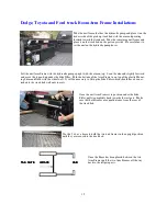
Страница 16: ...Dodge Toyota Section This section applies to the Boom Arm Frame installation on Ford Dodge and Toyota trucks only After finishing these steps proceed with the installation covered in the sec tions for hydraulic and electrical installation ...

Страница 17: ...unt ing Shim and flush with the wheel well It will be necessary to lift up the Side Filler which should have been at tached to the truck bed wall only loosely Use the 2 x 4 as a brace to hold the two unit frames in the upright position until they are secured to the truck bed Once the Brace has been placed between the two Arm Frames pull the two Arm Frames all the way back to the tailgate posts Onc...

Страница 18: ...hrough If the L Spacer was mounted correctly this hole will pass through the hole at the apex of the L Spacer Drill holes through the 2nd 3rd and 4th holes Now that the unit Arm Frames are secured to the Side Filler brackets undertake the following steps to attach the frames to the truck wheel wells Set the Three Hole Wheel Well Push the three 5 16 screws through the 3 Hole Bracket on the inside o...

Страница 19: ... and into the post of the pick up truck bed Next re move the bracket and use a 17 32 drill bit to widen the holes in the bed post in order to install the rivet nuts Installing Rivet Nuts Use the drill with the 5 16 drill bit and using the screw holes in the Vertical Post Mounting Bracket to align drill the holes into the side of the bed post After the holes are drilled remove the side bracket from...

Страница 20: ...ide holding the rivet nut Continue turning the wrench until it comes to a firm stop Reverse the socket wrench to break the tension in the tool Remove the socket and thread the screw out of the installed rivet nut Screw the top body into the bottom before installing another rivet nut We recommend performing a test installation before installing into your application Failing to perform a test could ...

Страница 21: ...scard the tie wraps secur ing the hose loops Feed the hoses down through the holes on the passenger side of the truck one hose per hole and pass them under the truck bed up through the two holes in the driver s side that are the farthest from the tailgate and set the ends next to the Pump Counter Balance Valve Remove the hose plugs with a 9 16 and a 1 2 inch open end wrenches Have a cloth or shop ...

Страница 22: ...side frame Roll the extra length of the hoses and use the smaller tie wraps to secure the coil Secure the front of the frame by tightening the screws on the front Boom Arm Frame Slide Brackets Loosen the screws holding the bracket to the frame Slide the bracket all the way to the bed side Tighten the screws Use the self tapping screws to secure the bracket to the wall of the bed Remove the small f...

Страница 23: ...nto the engine compartment and connect it to the other Fuse Terminal Place the Fuse Box cover on the Fuse Box and secure Run the long Power Cord under the truck bed and attach it to the chassis with the supplied tie wraps Feed the positive up through the remaining hole which should be the hole closest to the tail gate Attach the red power to the power terminal marked Line on the On Off Switch Run ...

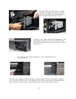
Страница 24: ...he arm on the pump side should move at a brisker pace than the other side Note It is important to watch the fluid level in the pump reservoir for the entire movement of the arms If the fluid level drops too low during the arm movement it will be necessary to bleed the system When the pump side arm reaches a height slightly above the cab roof hold the pump side arm down while depress ing the Boom O...

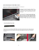
Страница 25: ...vided to refill the reservoir up to the level of the top reservoir indentation indicated by the black line in the illustration MOUNT THE WINCH CROSSBAR Back out the three screws that secure the Winch Terminal Block Cover Remove the cover and set it aside Place the crossbar in the arm bracket on the passenger side and do not secure A fish lead will extend out of the Winch Power Cable Feed Hole on t...

Страница 26: ...sbar to the unit arm brackets with the 5 16 x 4 bolts flat washers on top and bottom and the 5 16 nylon lock nuts The crossbar fit into the bracket is extremely tight It may be necessary to tap it in place with the rubber mallet Connect the Winch Power Cable leads to the winch terminal block The black lead connects to the red lead Connect the green lead to green the white to white and finally the ...

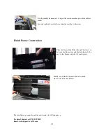
Страница 27: ... Construction The installation is complete and the unit is ready to lift load and go Technical Support call 713 589 9449 Email techsupport ezylift com Finally attach the Side Access Panels to both sides of the Unit Arm Frames Place the Frame Side Filler Except Chevrolet in between the Boom Arm and the bed side wall Se cure to the Frame with the 1 4 inch screws 25 ...

Страница 28: ...operation and ap plication conforming to good safety practices is the responsibility of the owner the user and its operating personnel It is the responsibility of the Owner Operator to require that all personnel that will install in spect test maintain and operate the Ezy Lift devise read the contents of this Owner s Manual Only those authorized and qualified personnel who have shown that they hav...

Страница 29: ...scoloration or de terioration Reject wire cable with kinking crushing bird caging or other distortions evidence of heat damage cracks deformation or worn end attachments six randomly broken wires in a single cable lay three broken wires in one strand of cable cracked hooks and hooks open more than 15 at the throat Ensure that the truck s cargo bed and suspension systems are in good condition i e s...

Страница 30: ...n to be per formed without having to move the vehicle Ideally the truck will be on level solid ground Make sure that there is adequate overhead clearance for the boom arms Step 2 Set the truck s parking brake and leave the engine running to prevent the battery from discharging Step 3 Open the truck tailgate This is very important to prevent damage to the truck or even the cargo In some instances i...

Страница 31: ...wrap the wire cable around the load Use a nylon sling or metal chain to secure the load to the hoist hook Wrapping the wire rope around the load and hooking it back onto itself can damage the cable and create a potential safety hazard Never attach a sling or chain link on the tip of the hoist hook or attempt to lift from the tip of the hook Make sure that the nylon or chain is properly seated in t...

Страница 32: ...th any mechanical product periodic inspection and maintenance is require keep the unit in optimal operating con dition Here are a few tips that owner operators should periodically perform to keep the unit in top op erating condition Please review this information If you should have any questions please con tact us during normal business hours Central Standard Time Monday through Friday exclud ing ...

Страница 33: ...o insure the correct wire rope replacement part obtain the part from Ezy Lift Use heavy leather gloves when handling the wire rope Do not allow the wire rope through bare hands Hydraulic Maintenance Ezy Lift s hydraulic unit is completely self contained and re quires no maintenance However periodic inspection of hy draulic cylinders hoses and fittings for any sign of leakage is recommended Periodi...

Страница 34: ...and or replace as necessary Inspect winch housing and motor for any signs of wear or problems repair or replace as nec essary TROUBLE SHOOTING Problem Possible Cause Possible Solution Lift Arms will not raise or lower Unit Off On switch is Off Turn the switch On A Remote Control assembly not properly plugged in Remove and re insert the Remote Control assembly B Poor electrical connection Check rep...

Страница 35: ... warranty This warranty does not cover breaking or fraying of the wire cable cost of labor for field repairs transportation charges in connection with replacement or re pairs of defective parts or nay damage as a result of misuse neglect overload ing accident improper installation maintenance or repair unauthorized altera tion or use of the product beyond the range of normal usage To obtain warran...

Страница 36: ...HYDRUALIC DIAGRAM 34 ...

Страница 37: ...35 ...

Страница 38: ...36 ...

Страница 39: ...37 ...

Страница 40: ...38 ...

Страница 41: ...39 ...

Отзывы: