Page F-2
Repair and Service Manual
B
ELECTRONIC SPEED CONTROL
Read all of Section B and this section before attempting any procedure. Pay particular attention to Notices, Cautions, Warnings and Dangers.
backwards slightly before again stopping in the stalled
condition. This process will repeat itself periodically until
the vehicles is moved from the stalled condition.
Example: If all of the following events occur...
a)
the system senses that the accelerator pedal is
depressed (power applied to motor)
b)
the brake is engaged so as to prevent vehicle
motion
the controller will sense a stalled motor condition and
remove power from the motor. When the brake pedal is
released, the vehicle will roll backwards slightly before
power is returned to the motor.
High Pedal Disable Feature
High pedal disable prevents undesired acceleration if
the direction selector lever is changed, or the key is
turned on while the accelerator is depressed.
Diagnostic Mode Feature
Diagnostic mode eases troubleshooting.
In the unlikely event of certain electrical system failures,
the controller will default to a mode that will permit the
vehicle to operate, but at a very reduced speed.
This feature allows the vehicle to be driven back to its
storage facility where the problem can be diagnosed.
The controller can be put in diagnostic mode by the
technician and the controller will report the failure mode.
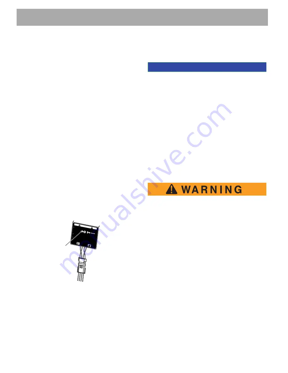
The two-position ‘Run-Tow/Maintenance’ switch is
located under the passenger seat (Ref Fig. 2).
Fig. 2 Run-Tow/Maintenance Switch
OPERATION
With the switch in ‘TOW/MAINTENANCE’ position:
•
the controller is deactivated
•
the electronic braking system is deactivated
which allows the vehicle to be towed or roll freely
•
the reverse warning beeper is deactivated
With the switch in ‘RUN’ position:
•
the controller is activated
•
the electronic braking system and reverse warn-
ing beeper features are activated
48 volt vehicles operate only in the ‘RUN’ position.
If all of the following events occur with the switch in ‘RUN’ posi-
tion
a)
the vehicle has been stopped for more than one
second
b)
the accelerator pedal has been released for more
than one second
c)
the vehicle begins to roll above 2 mph (3 kph)
the electronic braking will limit speed to approximately 2
mph (3 kph) and the warning beeper will sound. When
the accelerator pedal is depressed, the electronic brak-
ing and warning beeper will be overridden and normal
vehicle operation resumes. Any unusual situation
sensed by the 48 volt system will cause a similar
response. The system functions in all key switch posi-
tions.
To prevent the possibility of loss of control that
could cause severe injury or death, use service
brake to control speed. The controller system
is not a substitute for the service brake.
If all of the following events occur with the switch in
‘RUN’ position
a)
the vehicle is being driven down a slope
b)
the vehicle speed exceeds the designed speed
with the accelerator pedal depressed
or
released
(except options equipped with compression brak-
ing)
the electronic braking will limit the speed of the vehicle
to the designed speed range (the warning beeper will
not
sound). When the electronic braking system is acti-
vated by this sequence of events, the motor generates
power which is returned to the batteries. 48 volt models
are equipped with a regenerative motor control system.
The motor’s speed is sensed and regulated directly by
the controller. As a vehicle begins to accelerate while
descending a hill, the speed sensor will cause the motor
to electrically retard the speed of the vehicle through
regenerative braking.
TOWING
MAINTENANCE
Always select 'TOW / MAINTENANCE' position before towing.
After reconnecting batteries, allow a minimum of 30 seconds
before selecting 'RUN' position
To disable electrical system place switch in 'TOW/MAINTENANCE'
position and remove battery wire.
Possibility of electrical arc and battery explosion.
Before removing/connecting batteries or electrical components
turn switch to 'TOW/MAINTENANCE' position.
RUN
TOW
MAINTENANCE
WARNING
l
73340G01
Switch
NOTICE
Содержание EXPRESS L6 2012
Страница 6: ...Page iv Repair and Service Manual NOTES TABLE OF CONTENTS...
Страница 201: ......


