Page G-12
ENGINE
Repair and Service Manual
Read all of Section B and this section before attempting any procedure. Pay particular attention to all Notes, Cautions and Warnings.
B
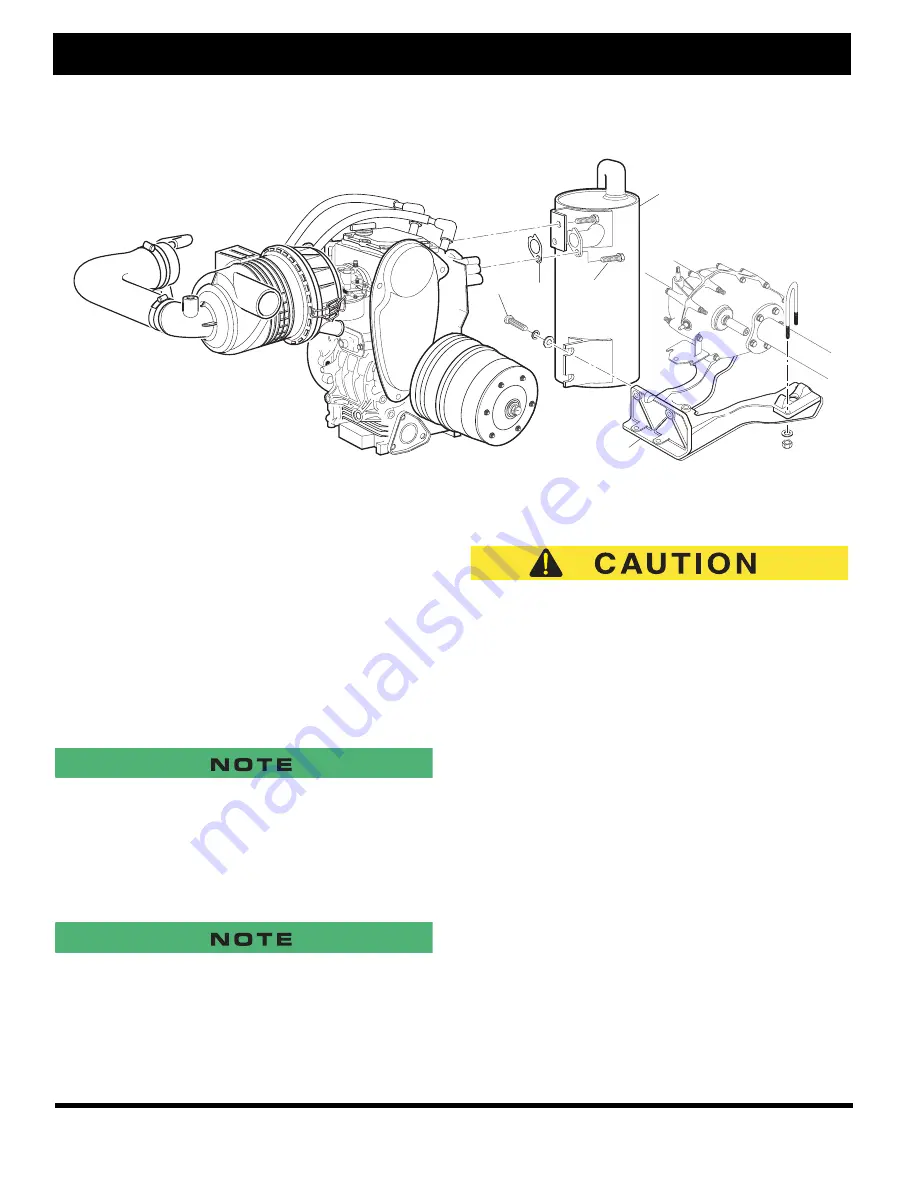
Fig. 23 Engine Assembly
Controls and Wiring
Unplug the wiring harness from the engine and cut the
wire tie securing the accelerator cable to the engine.
Remove the choke cable from the carburetor. Remove
the push nut at the governor and discard the nut.
Remove the pulse line from the fuel pump. Remove the
ground strap from the engine. Loosen the starter/gener-
ator and remove the belt. Remove the short control rod
from the bellcrank and the governor. Remove the short
rod from the bellcrank to the carburetor.
Removing the Engine from the Vehicle
Place suitable blocks under the engine frame for support.
Although the blocks are not required for engine removal, they
will help maintain the alignment of the frames and simplify
engine installation.
Loosen the bolt (3) securing the muffler (4) to the rear
engine frame (5) (Ref. Fig. 23 on Page G-12).
It is not necessary to remove the muffler as part of the engine
removal.
Remove the four bolts (15) that secure the engine to the
engine support castings (13, 17). Lift the engine and
drive clutch vertically through the engine compartment
using a hoist or with the assistance of another person.
Engine Installation
When installing the fuel and pulse lines, pay particular
attention to assure that the lines are not confused.
Be sure to use a new push nut when installing the accel-
erator cable to the governor.
It is important to follow the assembly sequence recom-
mended for mounting hardware.
With the assistance of a hoist or another person, lower
the engine into position over the engine support castings
(Ref. Fig. 24 on Page G-13).
Install one rear horizontal and one front bottom engine
bolt (15) through the casting and engine and lightly snug
in place.
Install the remaining horizontal engine bolts and finger
tighten. Remove the front bottom bolt and reinstall the
skid plate (8) finger tight.
Tighten the bottom and horizontal mounting bolts to 45
ft. lbs. (60 Nm) torque.
The remaining installation is in the reverse order of dis-
assembly using standard torque specifications.
1
2
3
4
5
Содержание 605586
Страница 1: ...GASOLINE POWERED GOLF CARS REVISED DATE JANUARY 2007 TECHNICIAN S REPAIR AND SERVICE MANUAL 605586 ...
Страница 6: ...Page iv Repair and Service Manual TABLE OF CONTENTS NOTES ...
Страница 10: ...Repair and Service Manual Page viii SAFETY INFORMATION NOTES ...
Страница 204: ...Page U 6 Repair and Service Manual GENERAL SPECIFICATIONS NOTES ...


