XTP R HWP 201 Wallplate Receiver • Installation
11
C
RS-232 Over XTP port
— To pass bidirectional serial or other control
signals between XTP-compatible devices, connect a control device to the
5-pole captive screw connector (see
figure 8
,
C
on the previous page). The
port includes only the 3 poles labeled “RS-232.”
IR Over XTP port
— To transmit and receive IR signals (up to 56 kHz),
connect a control device to the 5-pole captive screw connector (see
figure 8
,
C
on the previous page). This port includes the 2 poles labeled
“IR” and shares the ground pole with the RS-232 port.
NOTE:
RS-232 and IR data can be transmitted simultaneously (see
RS-232 and IR Over XTP Communication
on page 14 for wiring details).
D
LAN connector
— Connect a control device or device to be controlled to this
LAN connector (see
figure 8
,
D
on the previous page) for 10/100Base-T Ethernet
communication through this pass-through port. LEDs on this connector indicate link
and activity status.
E
Configuration port
— If desired, connect a host device to the front panel USB mini-B
Config port (see
figure 8
,
E
on the previous page) for configuring the receiver.
Connection Details
HDMI Connection
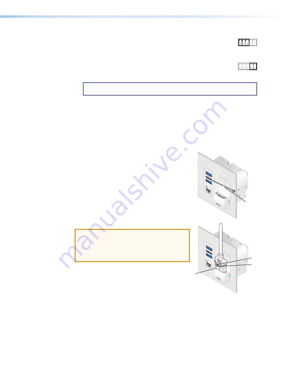
To secure the HDMI cable to the HDMI output connector,
use a tie wrap and the front panel lance punch.
1.
Route the tie clip through the front panel lance punch
(see
1
in the image to the right).
2.
Plug the HDMI cable into the panel connection (
2
).
3.
Loosely place the included tie wrap around the HDMI
connector (
3
).
4.
Use pliers or similar tools to tighten the tie wrap, then
remove any excess length (
4
).
ATTENTION:
•
Connect and pull the tie wraps until they are
secure. Do not overtighten.
•
Connectez et tirez les serre-câbles jusqu’à ce
qu’ils soient sécurisés. Ne pas trop serrer.
IR
Tx Rx G
Tx Rx
RS-232
IR
Tx Rx G
Tx Rx
RS-232
PW
R
SIG
L
R
AUDIO
RS-232
IR
OV
ER
XT
P
Tx
Rx
Tx
Rx
G
LAN
HDM
I OUT
AUD
IO
PW
R
SIG
L
R
AUDIO
RS-232
IR
OV
ER
XT
P
Tx
Rx
Tx
Rx
G
LAN
HDM
I OUT
AU
DIO
1
1
2
2
3
3
4
4


