background image


4

TLP Pro 1220, 1520, and 1720TG • Setup Guide (cont’d)

Rear Panel Features

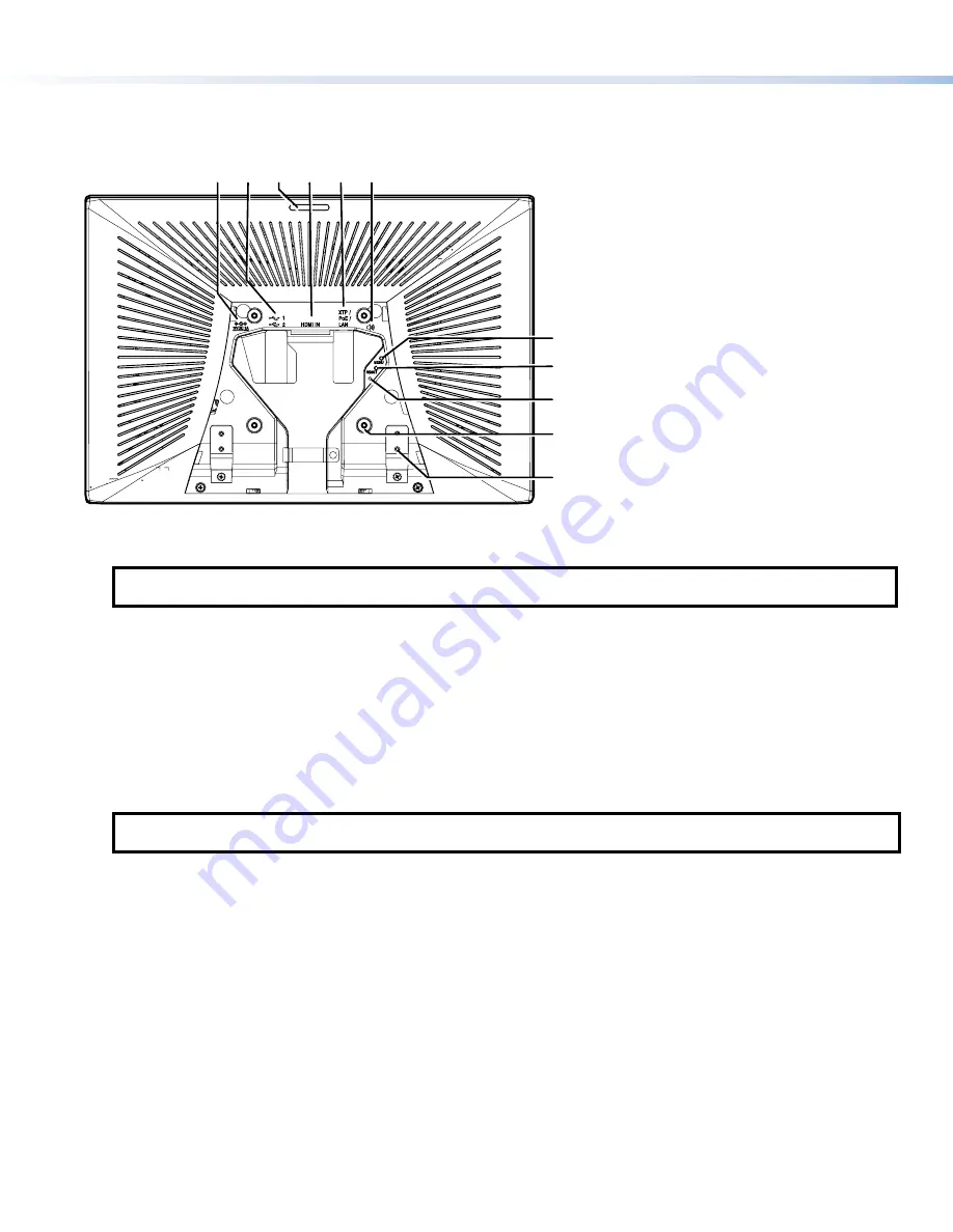
Figure 5 shows the TLP Pro 1720TG rear panel diagram (with back cover removed). The features of the TLP Pro 1220TG and 
TLP Pro 1520TG are very similar.

B

B

B

F

F

F

E

E

E

D

D

D

A

A

A C

C

C

I

I

I

H

H

H

G

G

G

J

J

J
K

K

K

B

B

B

F

F

F

E

E

E

D

D

D

A

A

A

C

C

C

I

I

I

H

H

H

G

G

G

J

J

J

K

K

K

Figure 5. 

TLP Pro 1720TG Rear Panel (with back cover removed)

A


Power supply input

 — connect a 12 VDC, 3.0 A Limited Power Source (LPS) power supply to this DC plug connector. 

NOTE:

  The TLP Pro 1720TG ships with the Extron PI 140 power injector included. For the TLP Pro 1220TG and 

TLP Pro 1520TG, either a 12 VDC, 3.0 A power supply or a power injector must be purchased separately.

B


USB connectors

 — for peripheral controls.

C


Rear status light

 — an LED light bar that can be programmed to provide system feedback.

D


HDMI input

 — for alternative video input.

E


XTP/LAN/PoE input

• 

XTP

 input — Connect the touchpanel to the XTP source using a twisted pair cable, terminated with an RJ-45 connector. 

For complete information about which cables to use, see the user guide for your XTP product.

• 

LAN

 input — Connect the touchpanel to the LAN using a twisted pair cable, terminated with an RJ-45 connector.

• 

PoE

 input — the connector can be used with a PoE power injector. Connect the cables as shown in figure 6, which shows 

the Extron PI 140 power injector (recommended by Extron).

NOTE:

  Some XTP models are able to remotely power these touchpanels but not all have that capability. Go to the 

Extron 

website

 and check the product page for your XTP model to ensure it can power your touchpanel.

An Extron IP Link Pro control processor must also be connected to the same network as the TouchLink Pro touchpanel.

F


Audio output

 — for use with headphones or assistive listening devices.

G


Menu button

 — activates the setup menu and calibration screen (see 

Setup Menu

 on the following page). 

H


Reset button

 —  pressing the reset button allows the unit to be reset in any of three different modes (see 

Reset Modes

, on the 

following page. For more information, see the 

TLP Pro 1220, TLP Pro 1520, and TLP Pro 1720 Series User Guide

).

I


Reset LED

 — provides feedback about the reset status when the user presses the reset button.

J


VESA mounting holes

 (4) — for use with D-type VESA mounting kits with the 100 x 100 mm mounting pattern.

K


Base attachment hinge

 (2) — each hinge secures the touchpanel to the base with two screws.

figure 5

note

Содержание TouchLink TLP Pro 1220 Series

Страница 1: ...words The factory configured passwords for all accounts on this device have been set to the device serial number Passwords can be changed during configuration Passwords are case sensitive NOTE If the device is reset to default settings the passwords are reset to the default password which is extron for either admin or user Make a note of the touchpanel MAC address Mount and Cable All Devices ATTEN...

Страница 2: ...ed with stands that allow the units to be placed on any suitable flat surface for example a desk table or lectern Fixed Mounting Figure 2 shows the base of the TLP Pro 1220TG with the cover removed to indicate the position of the mounting holes The bases of the TLP Pro 1520 TG and TLP Pro 1720TG are similar and the spacing of the mounting holes figure 2 1 is identical 1 Mark the location for two h...

Страница 3: ...e enabled and disabled using the Setup Menu see page 6 B Status light can be programmed to provide system feedback The LED light bar is located above the screen C Ambient light sensor monitors ambient light level and adjusts screen brightness D Capacitive touch screen provides simple control of AV systems The TLP Pro 1220TG has a 12 1 inch screen with a 1280x800 resolution The TLP Pro 1520TG has a...

Страница 4: ... your XTP product LAN input Connect the touchpanel to the LAN using a twisted pair cable terminated with an RJ 45 connector PoE input the connector can be used with a PoE power injector Connect the cables as shown in figure 6 which shows the Extron PI 140 power injector recommended by Extron NOTE Some XTP models are able to remotely power these touchpanels but not all have that capability Go to th...

Страница 5: ...y press the Reset button Use this mode to return the interface to factory default settings NOTES The factory configured passwords for all accounts on this device have been set to the device serial number Passwords can be changed during configuration Passwords are case sensitive If the device is reset to default settings the passwords are reset to the default password which is extron for either adm...

Страница 6: ... Audio Input and Advanced by pressing the appropriate button in the navigation bar at the top of the screen for more information see the TLP Pro 1220 TLP Pro 1520 and TLP Pro 1720 Series User Guide Figure 7 shows the setup menu for the TLP Pro 1220TG The setup menus for the TLP Pro 1520TG and TLP Pro 1720TG are very similar Press the Menu button for at least 3 seconds to open the calibration scree...

Отзывы: