background image

3

Step 3 — Run all Cables

Run all cables necessary to support the AC connector, the cables stored in the cubby, and all planned AAP connectors. Run the 
cables below the table and through the hole that was cut in Step 2. Leave enough slack in the cables to connect or route them 
before the cubby is installed in the table. Leave enough space under the enclosure for the external power supply and connection 
of AV cables and the network connection for the TLP 710CV.

Step 4 — Install Cable Retractors (Optional)

If required, Extron cable retractors should be installed in the 
enclosure at this stage. For complete information about retractors 
and how to install them, see the 

Retractors User Guide

, which is 

available from the Extron website (

www.extron.com

).

Step 5 — Install Power Module (Optional)

NOTE:

  For models that do not include a power module, see the 

Extron website to select a power module that is suitable for 
your location.

The power module takes up two or three AAP spaces, depending on 
the model, and may be installed before or after the AAP assembly is 
installed. It may be installed with AAPs on either side. 

1. 

Secure the power module into position with #4-40 Phillips head 
screws and star washers.

CAUTION:


Risk of electric shock:

 To ensure good 

electrical grounding, you must use the star washers with 
the screws.

2. 

Run the cable or conduit to a convenient junction box.  
Extron recommends the circuit be attached to a junction 
box that is directly wired to the main circuit.

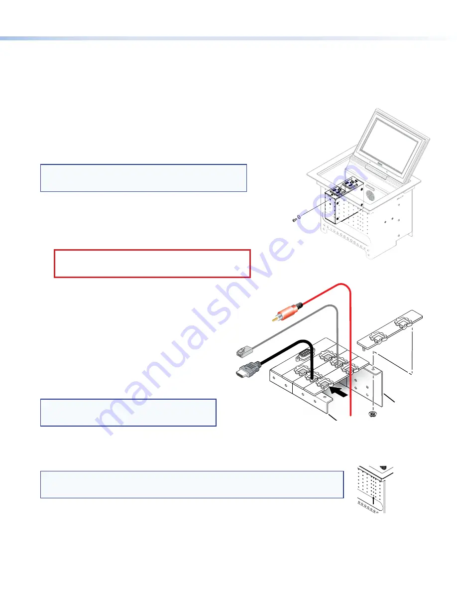
Step 6 — AAP Assembly

Install all desired cables into the cable pass-through AAPs and 
install the AAPs into the Cable Cubby. 
The simplest way to install the cables and AAPs is to populate 
the AAP brackets outside the cubby and then install the 
populated AAP shelf assembly into the cubby.
Install cables in the pass-through holes as shown in the figure 
to the right.

TIP:

   Hand tightening the #4-40 nuts makes it easier 

to place and secure the assembly inside the 
enclosure.

NOTE:

  An extra column of AAP bracket mounting points is available for use with TLP Single-

space AAP mounting brackets (part number 

70-693-01

). Single-space brackets will not fit in 

any other location.

Secure the power module

to the TLP 710CV frame

with #4-40 Phillips head

screws and star washers.

Rear Brackets

Front Brackets

The extra column
of mounting points
is for installing
single-space
AAP brackets.

Содержание TouchLink TLP 710CV

Страница 1: ...y Ensure there is enough space for all the system cables and components including cable retractors if they are to be installed Decide on the method for cutting a hole in the table z z Hand router and template z z CNC wood router z z Jigsaw and paper template Verify that you have the correct template or dimensions Check all relevant regulations z z Ensure the installation complies with local state ...

Страница 2: ... see Preparing the Table in the TLP 710CV User Guide There are three methods for cutting the hole in the table Using a hand router Recommended method Use the Extron TLP 710CV routing template part number 70 980 01 Refer to the Routing Template User Guide available at www extron com to prepare the template and use the template to cut the hole NOTE The metal router guide must be purchased separately...

Страница 3: ... installed with AAPs on either side 1 Secure the power module into position with 4 40 Phillips head screws and star washers CAUTION Risk of electric shock To ensure good electrical grounding you must use the star washers with the screws 2 Run the cable or conduit to a convenient junction box Extron recommends the circuit be attached to a junction box that is directly wired to the main circuit Step...

Страница 4: ...ution when handling and mounting the enclosure 1 Remove the edge grommet protecting the edges of the trim ring and the plastic film on the finished surfaces ATTENTION Do not use isopropyl alcohol or other solvents to clean the Cable Cubby Strong solvents will ruin some finishes 2 Carefully lower the enclosure into the hole cut in the table see Step 2 Cut the Surface on page 2 Ensure the trim ring ...

Страница 5: ...he wrong voltages into a socket will damage the TLP 710CV Connecting to the Network Directly Using an external 12 VDC Power Supply If the PoE power supply is not used run a straight through cable from the LAN PoE connection b to a network switch or router Connecting to a Power over Ethernet Power Supply 1 Use a straight through LAN cable to connect the LAN IN socket to a network switch or router 2...

Страница 6: ... on page 8 c MTP Video Signal Adjustments Three MTP signal adjustments are available for S video luminance gain VID Y S video chrominance gain C and sharpness S For composite video signals the VID Y adjustment controls the gain d Reset LED provides feedback about the mode status when the user presses the reset button e Controller Communication LED is unlit during normal operation The LED blinks re...

Страница 7: ...ifferent screens Main Volume Time Network and Video that can be selected by pressing the appropriate button at the left side of the screen There is also an Exit button at the bottom left corner of the screen for saving changes and leaving the menus Use the screens to adjust the following options for more information see the TLP 710CV User Guide Main Adjusts the Sleep timer Backlight and Auto Backl...

Страница 8: ...button in the top left corner highlighted Press and Hold Highlighted Box Until Color Changes 2 Press the highlighted button until it turns gray and a new button is highlighted When all four points have been calibrated the screen reopens to the Main Screen 3 Press Exit to close the on screen menus 4 Reattach the bezel Reset Modes The touchpanel has four reset modes Factory Firmware Mode Run or Stop...

Отзывы: