background image

6

IPL EXP I/O Series • Setup Guide (Continued)

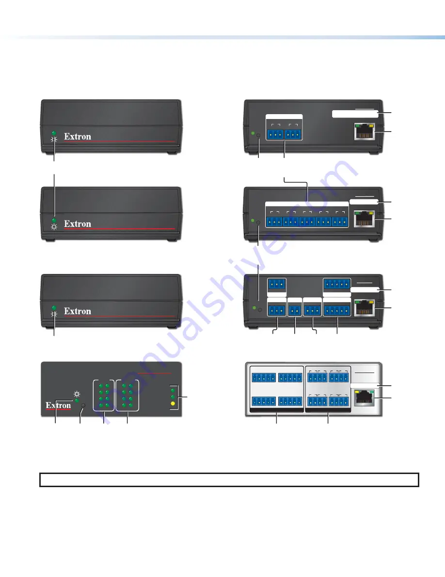
Panels and Locations of Features

Location and quantity of LEDs and corresponding connectors vary by model, but the functions and port wiring are identical 
across models for each port type.

Front Panel Features

IPL EXP RIO8

100

LINK

ACT

3

4

1

2

3

4

1

2

7

8

5

6

7

8

5

6

RELAYS

I/O

IPL EXP 200

IPL EXP S2

IPL EXP S5

Reset 

Button

(recessed)

Power 

LED

Power 

LED

Power 

LED

Relay 

LEDs

Digital

I/O 

LEDs

LAN/ 

Network

LEDs

Figure 2. 

 IPL EXP I/O Series Front Panels

Rear Panel Features

IPL EXP RIO8

1   2   12V24V G

3   4   12V24V G

RELAYS

3

4

7

8

1

2

5

6

+V OUT / DIGITAL I/O

5   6   12V24V G

7   8   12V24V G

12 VDC / 24 VDC

19W MAX TOTAL

LAN / PoE+

LAN/PoE

IPL EXP S2

Tx Rx G

COM

Tx Rx G

RESET

1

2

LAN/PoE

IPL EXP S5

Tx Rx G

COM

Tx Rx G

RESET

1

2

Tx Rx G

Tx Rx G

3

4

Tx Rx G

5

LAN/PoE

IPL EXP 200

+V +S -S G

Tx Rx G

eBUS (PWR 3W)

RELAYS

1 2 C

COM 2

1 2 3

G

Tx Rx G

DIGITAL I/O

COM 1

4

RESET

IR/S

S G

MAC: 00-05-A6-

XX-XX-XX

S/N:  #######    E######

MAC: 00-05-A6-

XX-XX-XX

S/N:  #######    E######

00-05-A6-XX-XX-XX

MAC: 00-05-A6-

XX-XX-XX

S/N:  #######    E######

MAC: 00-05-A6-

XX-XX-XX

S/N:  #######    E######

COM 

RS-232 

ports

COM 

RS-232 

ports

MAC

address

MAC

address

Relay 

ports

Relay 

ports

MAC

address

MAC

address

Digital I/O

 ports with 

12 VDC

 and 

24 VDC

output ports

LAN/PoE

(Ethernet) 

connector 

and LEDs

LAN/PoE

(Ethernet) 

connector 

and LEDs

LAN/PoE

(Ethernet) 

connector 

and LEDs

LAN/PoE

(Ethernet) 

connector 

and LEDs

IR/Serial 

output

port

eBUS

port

Reset Button

(recessed)

and LED

Reset 

Button

(recessed)

and LED

Figure 3. 

IPL EXP I/O Series Rear Panels

NOTE:

  For full reset mode information, see the 

IPL EXP I/O Series User Guide

.

Содержание IPL EXP I/O Series

Страница 1: ...Panels NBPs and IPL EXP expansion interfaces over a standard Ethernet network Global Configurator and other useful software applications are available at www extron com Setup Checklist How to Proceed With Installation Get Ready Familiarize yourself with the features of the IPL EXP Expansion Iinterface see Front Panel Features on page 6 Rear Panel Features on page 6 and of any IPCP Pro xi Series co...

Страница 2: ...tion The help file for GC includes an introduction to the software and how to start a project and configuration If TouchLink Pro or third party touchpanels are part of the system start and use GUI Designer to design save and build the graphical user interface GUI layout for the touchpanels NOTE To redeem activate a LinkLicense go to www extron com llredeem and follow the online instructions Using ...

Страница 3: ...User Guide and the IPL EXP I O Series User Guide for an outline of the system testing procedure Make adjustments to wiring or configuration as needed Network Communication Setup Network setup is essential prior to configuration Use the flowchart at right as a guide to setting up the expansion interface for network use NOTE If using 802 1X security see the Extron 802 1X Technology Reference Guide a...

Страница 4: ...es in the bottom of the IPL EXP with the holes in an Extron rack shelf and fasten the unit to the shelf with two 4 40 x 3 16 inch screws see 1 at right 2 Bolt the rack shelf to the rack see 2 Mounting an IPL EXP Expansion Interface With a ZipClip 200 These instructions apply to the IPL EXP 200 S5 and S2 models 2 4 40 x 3 16 Screws RSB 123 Rack Shelf On a Rack Shelf 2 1 Using the ZipClip 200 Attach...

Страница 5: ...e Inside Rack Side of Rack ZipClip 200 Back of Rack Furniture mounting NOTE The ZipClip is shipped with a set of four wood screws 1 Attach the ZipClip to the mounting surface using two or more wood screws see 1 below Make sure the clip is oriented with the appropriate side facing the mounting surface of the furniture and with the tab accessible from the front of the furniture 2 Insert the EXP into...

Страница 6: ... S2 Tx Rx G COM Tx Rx G RESET 1 2 LAN PoE IPL EXP S5 Tx Rx G COM Tx Rx G RESET 1 2 Tx Rx G Tx Rx G 3 4 Tx Rx G 5 LAN PoE IPL EXP 200 V S S G Tx Rx G eBUS PWR 3W RELAYS 1 2 C COM 2 1 2 3 G Tx Rx G DIGITAL I O COM 1 4 RESET IR S S G MAC 00 05 A6 XX XX XX S N E MAC 00 05 A6 XX XX XX S N E 00 05 A6 XX XX XX MAC 00 05 A6 XX XX XX S N E MAC 00 05 A6 XX XX XX S N E COM RS 232 ports COM RS 232 ports MAC a...

Страница 7: ...r the IPL EXP RIO8 NOTE The IPCP Pro 360Q xi offers Power over Ethernet PoE output on AV LAN ports 2 and 3 These RJ 45 connectors labeled PoE Out can output a maximum of 30 watts per port It can be used to power the IPL EXP extension interface The rest of the IPL EXP I O Series expansion interfaces IPL EXP 200 IPL EXP S5 IPL EXP S3 accept power over Ethernet PoE or PoE through the LAN port in addi...

Страница 8: ...inée à une utilisation en intérieur uniquement Elle doit être connectée seulement à des réseaux ou des circuits qui ne sont pas routés au réseau ou au bâtiment extérieur MAC address Each IPL EXP expansion interface is assigned a unique user hardware ID number MAC address for example 00 05 A6 05 1C A0 You may need this address during configuration A label that indicates the MAC address is located o...

Страница 9: ...Control Unidirectional Digital I O 1 2 12V24V G 3 4 12V24V G V OUT DIGITAL I O 5 6 12V24V G 7 8 12V24V G 12 VDC 24 VDC 19W MAX TOTAL V S S G eBUS PWR 3W 1 2 3 G DIGITAL I O 4 3 4 1 2 7 8 5 6 I O Digital I O digital input output Configure each port as a digital input or output with or without 5 VDC pull up Use these ports to Monitor or trigger events and functions toggle relays issue commands send ...

Страница 10: ...wer 12 VDC Occupancy Control Output Ceiling Ceiling Tile Hanger Clip Extron OCS 100C Occupancy Sensor Extron IPL EXP RIO8 Expansion Interface LAN PoE LAN Extron ECM S10 Rx Receiver does not detect signal from transmitter ECM S10 Tx Partition closed The IPL EXP RIO8 includes both 12 VDC and 24 VDC output ports for use together with the digital I O ports to provide power to small accessories They re...

Страница 11: ...els for intuitive control of the system once the panels are configured The port is always on unless the total load reaches the overload condition Global Configurator software provides a way to monitor these ports Normal operation mode The load drawn by connected devices is below the maximum power threshold Limit mode The total load at this port has reached the maximum threshold power Overload mode...

Страница 12: ...following the fifth press Use this mode to enable or disable the DHCP client for the LAN port The Power or Reset LED blinks 6 times if the DHCP client is enabled The Power or Reset LED blinks 3 times if the DHCP client is disabled NOTES By default DHCP is off for the LAN port and the unit uses a static IP address If DHCP has been enabled when you disable DHCP the unit reverts to using the previous...

Страница 13: ...n com Via links from the web page for the specific product Via the Download page Click on the Download tab at the top of any page within www extron com Via links from search results NOTES For some software you have the option to click the Download Now button to begin downloading the software file For other software there is a link for contacting an Extron support representative who can provide you...

Страница 14: ...ouchpanels or other interfaces Test the system make adjustments finalize configuration Save the project Build and upload the configuration to the control processor If desired or required use Toolbelt or other software to configure security settings for 802 1X SSL Upload security certificates private keys Create a new GC Professional or GC Plus project and add the control processor to it Within Glo...

Отзывы: