


3
on page 1)— In a system with a DTP2 transmitter, set the toggle switch to the
Send
OFF
SEND
POWER
position (up) on the powered unit to enable sending power to the unpowered unit. Set the toggle switch to the
Off
position (down) on the DTP2 unit that is to receive power.
ATTENTION:
•
The DTP2 device is configured to output power to DTP2 models only. If connected to a legacy DTP device, set the toggle
switch to the
Off
position (down). Failure to turn the power off will damage the connected legacy DTP device.
•
Le DTP2 est configuré pour fournir une alimentation aux modelèles legacy DTP uniquement. S’il est connecté à un autre
appareil, veuillez positionner l’interrupteur à bascule sur «
Off
»(down). Si l’interrupteur n’est pas positionné sur off, vous
risquez d’entraîner la défaillance de l’appareil non DTP2 connecté.
NOTES:
•
The DTP2 R 212 SA must always be powered locally, but can send power to the connected transmitter.
•
The DTP2 R 212 (non SA model) can either receive from or send power to the connected receiver.
— Initiates four levels of switcher reset. See the
DTP2 R 212 Series User Guide
, available
R
.
Front panel
e
CONFIG
AUTO
SWITCH
A
Figure 2.
Front Panel Configuration Port
A
Configuration port
— This USB mini-B port serves a similar communications function as the rear panel Remote port, but it is easier
to access than the rear port after the switching receiver has been installed and cabled.
NOTE:
A front panel Configuration port connection and a rear panel Remote port connection can both be active at the same
time. If commands are sent simultaneously to both, the command that reaches the processor first is handled first.
Operation
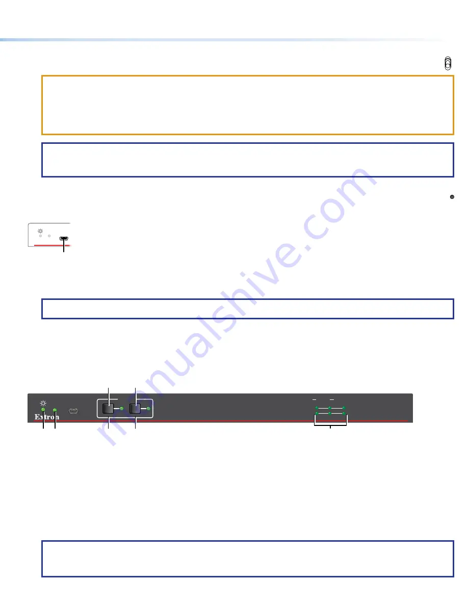
Front Panel Features
All DTP2 R 212 models share a common front panel (see figure 3).
DTP2 R 212 SERIES
CONFIG
AUTO
SWITCH
INPUTS
OUTPUT
1
2
SIGNAL
HDCP
INPUTS
1
MODE
NORM/AUTO
2
C
C
A B
D
E
F
Figure 3.
Front Panel Features
A
Power LED
(see
B
Auto Switch LED
C
Input buttons and LEDs
A
Power LED
— Lights when power is applied.
B
Auto switch LED
— Lights when the device is in auto switch mode (see
C
Input buttons and LEDs
— Press and release to select the associated input. The LED indicates the selection.
NOTES:
•
The switcher must be in manual switch mode (Auto Switch LED [
B
] unlit) to select an input with these buttons.
•
These buttons also select the auto or manual switch mode (see
D
and
E
on page 4 and
).


