


Altitude 4522 Access Point External Antenna Model Antenna Options
Altitude™ 4522 Series Access Point Installation Guide
23
Suspended Ceiling Mount Hardware
●
Security cable (optional)
●
Mounting ears
●
Customer supplied pipe or channel clamps
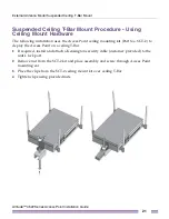
Ceiling Mount Procedure
1
If possible, remove the ceiling tile from its frame and place it, finish side down, on a
work surface.
2
If required, install and attach a Kensington security cable (customer provided) to the
unit’s lock port.
3
Place the Access Point on the ceiling tile or attach to a plenum beam or pipe using
industry available clamps.
4
Attach appropriate antennas to the connectors.
5
Bring the tile into the ceiling space.
6
Attach an Ethernet cable from the Access Point to a controller with an 802.3af compatible
power source or use the PWRS-14000-148R power supply to supply power to the
Altitude 4522 Access Point (once fully cabled).
7
Verify that the Access Point is receiving power by observing the LEDs.
8
Place the ceiling tile back in its frame.
CAUTION
If you are not using a 802.3af capable controller to power the Altitude 4522 Access Point,
ensure that only the Altitude 4522 Access Point’s designated power supply (PWRS-14000-148R) is
used. Using an incorrectly rated power supply could damage the unit and void the product warranty.
Do not actually connect to the power source until the cabling portion of the installation is complete.
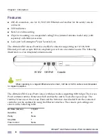
Altitude 4522 Access Point External Antenna
Model Antenna Options
Extreme Networks supports two antenna suites for Altitude 4522 Access Point External
Antenna models. One antenna suite supporting the 2.4 GHz band and another antenna suite