Exmark LAZER Z UVD60 Скачать руководство пользователя страница 9

Page 9 of 13 

109-4195 Rev. A 

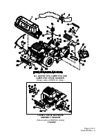
16.  Reinstall the deck drive belt in the lower groove of 

the double sheave.  Install plug (Item 40) into 
bore of double sheave. 

17.  Remove the discharge chute from the deck.  

Discard the mounting hardware, but save the 
discharge chute for use during side discharge 
operation.  The chute pivot pin (Item 21) and 
hairpin (Item 22) may be stored in the pivot holes 
on the discharge chute during bagging operation.


Units 600,000 and Higher: 

18.  Lower the deck fully.  Remove the right hand belt 

cover.  Remove the belt cover mounting stud that 
protrudes from the deck.  Save the knob for later 
use. 

19.  Remove the blade from the right spindle. 

20.  Insert special tool 109-2979 into splined end of 

spindle shaft. 

21.  Remove the right sheave nyloc nut, washer, and 

splined washer from the spindle shaft.   Do not 
remove the blade drive sheave.  Retain the nut for 
later use. 

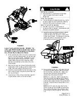
Use special tool 109-2979 to hold spindle from 
rotating.  Do not use the blade bolt to prevent 
rotation. 

22.  Install the Ultra Vac drive sheave onto the right 

spindle shaft.  Install the washer that is supplied 
with the Ultra Vac drive kit (Item 38) and nut 
removed in step 4.  Torque the sheave nut to:  
5/8-18 Nut (15/16 Hex) 90-110 ft-lbs.   

Use special tool 109-2979 to hole spindle from 
rotating


(See Figure 10).  Do not use the blade 

bolt to prevent rotation. 


FIGURE 10 

Reinstall blade and torque bolt to:  For units 
with a 1/2-20x2 blade bolt, torque to 50-60 ft-
lbs (75-81 N-m). 

23.  Reinstall the deck drive belt in the lower 

grove of the double sheave.  Install plug 
(Item 40) into bore of top sheave. 

24.  Remove the discharge chute from the deck.  

Discard the mounting hardware, but save the 
discharge chute for use during side discharge 
operation.  The chute pivot pin (Item 21) and 
hairpin (Item 22) may be stored in the pivot 
holes on the discharge chute during bagging 
operation.  

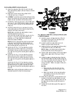
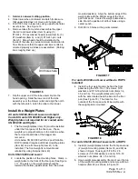
25.  Install deflector (Item 46) at the front right 

corner of deck as shown in Figure 11. Use 
carriage bolt, nut and washer that retains right 
corner of adjustable front baffle. 


FIGURE 11 

26.  Install the belt cover mounting stud (Item 27). 

For 60” units only, install the spacer (Item 
29), two 7/16 spring disk washers (Item 30) 
and the plastic knob (See Figure 12).  The 
knob does not need to be tightened 
against the washers at this time. 


FIGURE 12 

27.  Install the mounting pin weldment (Item 18) to 

the blower assembly using the 3/8-16 x .75 
bolts (Item 28) and whizlock nuts (Item 24).  
Maximum deck clearance will be provided if 
the bolts are installed from below the 

Содержание LAZER Z UVD60

Страница 1: ...0 000 Higher 109 1167 Drive Kit Lazer Z XS Air Cooled 605 Triton 600 000 Higher 109 1167 Drive Kit Lazer Z XS Liquid Cooled 605 Triton 600 000 Higher 109 1167 Drive Kit and 109 2203 Floor Pan Weight Lazer Z 665 Triton 600 000 Higher 109 1168 Drive Kit Lazer Z XS Air Cooled 665 Triton 600 000 Higher 109 1168 Drive Kit Lazer Z XS Liquid Cooled 665 Triton 600 000 Higher 109 1168 Drive Kit and 109 220...

Страница 2: ...n large 4 4 4 4 4 21 Chute Pivot Pin 1 1 1 1 1 22 Hair Pin small 1 1 1 1 1 23 3 8 16 x 1 00 Hex Screw 13 16 16 12 12 24 3 8 Whizlock Nut 16 19 19 15 15 25 3 8 Spring Disk Washer 13 16 16 16 16 26 Handle Mount Weldment 1 27 Belt Shield Stud 1 1 1 1 1 28 3 8 16 x 75 Hex Screw 3 3 3 3 3 29 Belt Cover Spacer 1 60 only 1 60 only 1 60 only 1 60 only 1 60 only 30 7 16 Spring Disk Washer 2 60 only 2 60 on...

Страница 3: ...Page 3 of 13 109 4195 Rev A FIGURE 1 LAZER Z SN 352 000 509 999 ASSEMBLY DIAGRAM Shown without ROPS for clarity ALL LAZER Z XP LAZER Z XS AND LAZER Z SN 510 000 HIGHER Shown without ROPS for clarity ...

Страница 4: ...a liquid cooled Lazer Z the rear bumper plate must be removed Remove rear bumper plate Reattach the lower side bumper bars to the vertical HOT engine guard shield using two of the original screws washers and whizlock nuts removed from the bumper plate 3 Remove the lower two screws holding the clutch guard plate HOT engine guard on liquid cooled units to the rear frame of the Lazer Z unit 4 Install...

Страница 5: ...us WHAT CAN HAPPEN The mechanical or hydraulic jacks may not be enough support or may malfunction allowing the unit to fall which could cause injury HOW TO AVOID THE HAZARD DO NOT rely solely on mechanical or hydraulic jacks for support Use adequate jack stands or equivalent support 12 Install the right and left hand frame brackets Items 14 and 15 loosely to the mount weldment and wheel channels o...

Страница 6: ...s shown it will be necessary to push the capscrew through the masking tape applied in step 14 Install one 3 8 16 x 4 1 2 hex capscrew spring disk washer and 3 8 16 whizlock nut through the top tube as shown it will be necessary to push the capscrew through the masking tape applied in step 14 NOTE Be sure the spring disk washer cone is installed towards the head of all capscrews FIGURE 5 For All La...

Страница 7: ...f the spring disk washer faces the head of the screw See Figure 7 Lazer Z units with SN 352 000 509 999 only 32 Remove the E clip and handle from the handle assembly Item 7 Discard the mount that came with the handle assembly Install the handle and E clip onto the handle mount Item 26 that came in the completing kit 33 Mount the handle assembly Item 7 onto left hand frame bracket Item 15 using 3 8...

Страница 8: ...s 156 163 N m 7 Re install the deck drive belt in the lower groove of the double sheave Install the plug Item 40 into the bore of the double sheave 8 Remove the discharge chute from the deck Discard the mounting hardware but save the discharge chute for use during side discharge operation The chute pivot pin Item 21 and hairpin Item 22 may be stored in the pivot holes on the discharge chute during...

Страница 9: ...p 4 Torque the sheave nut to 5 8 18 Nut 15 16 Hex 90 110 ft lbs Use special tool 109 2979 to hole spindle from rotating See Figure 10 Do not use the blade bolt to prevent rotation FIGURE 10 Reinstall blade and torque bolt to For units with a 1 2 20x2 blade bolt torque to 50 60 ft lbs 75 81 N m 23 Reinstall the deck drive belt in the lower grove of the double sheave Install plug Item 40 into bore o...

Страница 10: ...On 60 and 66 units the outside end of the cover is slotted and can slip between the two washers assembled in step 26 The plastic knob does not need to be removed On 72 units the cover has a hole and the plastic knob must be installed after the cover has been positioned On Units SN 600 000 and Higher with Triton decks 32 Adjust dog leg baffle to match Ultra Vac blower intake opening Adjusting too w...

Страница 11: ...le ROPS installed require additional mounting plates Item 42 and a front weight Item 41 to be installed The front weight is removable and retained by using hairpins Item 43 Units SN 439 999 and Lower 2 Locate the position of the mounting holes Clamp a weight plate to the front of the floor pan See Figure 17 The ears on the weight plate should be towards the bottom upside down from the actual mount...

Страница 12: ... Items 34 35 and 36 The weight plates will only fit with the ears located near the bend in the floor pan See Figure 17 The decal on the outside of the floor pan will still be visible with the weight plates mounted Install the Removable Weights Note The removable weights are heavy Use care when lifting them Make sure that you can hold them securely before lifting them Use caution when positioning y...

Страница 13: ...hat the blower drive operates correctly prior to delivery to customer 2 The Ultra Vac blower operates when deck drive is engaged Be sure that all persons are clear of the mower deck and blower before engaging the cutting blades Set the throttle to midway position Pull outward on the PTO switch to the ROTATE position 3 To disengage the deck drive and blower set the throttle to midway position Push ...

Отзывы: