


Page 13 of 13
109-4195 Rev. A
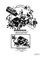
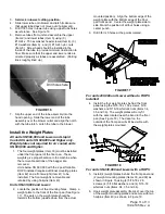
FIGURE 21
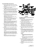
Operation
Pre-Start
1. Read the operator’s manual for the mower
and Ultra Vac to familiarize yourself with all
controls before operating the machine. Make
sure that you understand the controls, their
locations, their functions, and their safety
requirements.
2. Ensure the blower, belt cover, bags, tube and
hood are in good condition, properly attached,
and latched.
Run In
1. Verify that the blower drive operates correctly
prior to delivery to customer.
2. The Ultra Vac blower operates when deck
drive is engaged. Be sure that
all
persons are
clear
of the mower deck and blower
before
engaging
the cutting blades. Set the throttle
to “midway” position. Pull outward on the
PTO switch to the “ROTATE” position.
3. To disengage the deck drive and blower, set
the throttle to “midway” position. Push in on
the PTO switch to the “STOP” position to stop
the cutting blades and blower. The cutting
blades will require a slightly longer amount of
time to come to a complete stop when the
blower is installed on the deck.


