


Page 11 of 13
109-4195 Rev. A
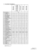
3.
Set deck in lowest cutting position.
4. Slide lower tube onto blower and latch (make sure
that upper tube does not move out of alignment).
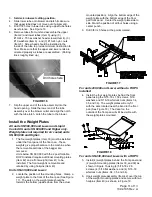
5. Drill 7/32 holes in lower tube using upper tube holes
as reference. See Figure 16.
6. Remove tubes from unit and assemble the upper
(Item 2) and lower tubes (Item 3) using (3)
#10-24 x .75 hex washer head screws (Item 4), (3)
#10 washers (Item 6) , and (3) #10-24 nyloc nuts
(Item 5). Screw head should be installed to the
inside of the tube to provide minimum obstruction to
flow. Make sure that the upper and lower ends are
oriented properly as tubes are assembled. (Parting
lines roughly lined up.)
FIGURE 16
7. Slip the upper end of the tube assembly into the
hood opening. Slide the lower end of the tube
assembly over the blower outlet and align the notch
with the tube latch. Latch the tube to the blower.
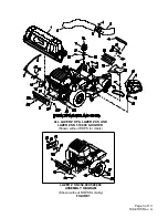
Install the Weight Plates
All units SN 599,999 and Lower and Liquid
Cooled XS units SN 600,000 and Higher only.
Weight plates not required for air cooled units
SN 600,000 and Higher.
1. The four weight plates (Item 33) must be installed
under the front panel of the floor pan. These
weights give proper balance to the machine when
the removable portions of the bagger are
removed.
Units below SN 600,000 with the 2 post foldable
ROPS installed require additional mounting plates
(Item 42) and a front weight (Item 41) to be
installed. The front weight is removable and
retained by using hairpins (Item 43).
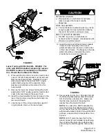
Units SN 439,999 and Lower:
2. Locate the position of the mounting holes. Clamp a
weight plate to the front of the floor pan (See Figure
17). The ears on the weight plate should be
towards the bottom (upside down from the actual
mounted position). Align the bottom edge of the
weight plate with the bottom edge of the floor
pan front panel. Center the weight plate side to
side. Mark the position of all four holes using a
center punch.
3. Drill 3/8 inch holes at the points marked.
FIGURE 17
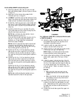
For units 439,999 and Lower without a ROPS
installed:
4. Install the four weight plates behind the front
panel using the 5/16-18 x 1.50 screws, 5/16
washers and 5/16-18 whizlock nuts (Items 34,
35, and 36). The weight plates will only fit
with the ears located near the bend in the floor
pan (See Figure 18). The decal on the
outside of the floor pan will still be visible with
the weight plates mounted.
FIGURE
18
For units SN 439,999 and Lower with a ROPS
:
5. Install (4) weight plates behind the front panel and
(2) weight mounting plates (Items 33, and 39) as
shown in Figure 16 using (4) 5/16-18 x 2.0
screws, (4) 5/16 flat washers, and (4) 5/16-18
whizlock nuts (Items, 34, 35, and 36).
6. Hook weight plate assembly (Item 42) over the top
of the weight mounting plates and secure with two
hairpins (Item 43) as shown in Figure 19.
Drill holes here


