


Page 12 of 13
109-4195 Rev. A
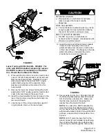
Note: The removable weight is heavy. Use
care when lifting. Make sure that you can hold
the weight securely before lifting. Use caution
when positioning your hands so that you do
not set the weight down on your hands or
fingers.
FIGURE 19
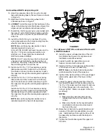
For units SN 440,000–599,999:
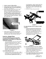
7. Locate the position of the mounting holes by
aligning the template (P/N 103-5865) on the front
face of the floor pan as shown in Figure 20.
Clamp the template in place. Using a center
punch, mark the positions of the holes on the floor
pan. Flip the template over and repeat on the
other end of the floor pan face.
FIGURE 20
8. Drill 3/8” holes at the points marked.
9. Follow steps 5 through 6 for weight installation
(See Figure17).
For Lazer XS Liquid Cooled units SN 600,000
and Higher:
10. Locate the position of the mounting holes by
aligning the template (P/N 103-5865) on the front
face of the floor pan as shown in Figure 18.
Clamp the template in place. Using a center
punch, mark the positions of the holes on the floor
pan. Flip the template over and repeat on the
other end of the floor pan face.
11. Drill 3/8” holes at the points marked.
12. Install the four weight plates behind the front
panel using the 5/16-18 x 1.50 screws,
5/16 washers and 5/16-18 whizlock nuts
(Items 34, 35, and 36). The weight plates will
only fit with the ears located near the bend in
the floor pan (See Figure 17). The decal on
the outside of the floor pan will still be visible
with the weight plates mounted.
Install the Removable Weights
Note: The removable weights are heavy. Use
care when lifting them. Make sure that you can
hold them securely before lifting them. Use
caution when positioning your hands so that you
do not set them down on your hands or fingers.
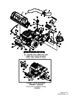
1. Assemble the weight brackets (Item 31) to the
removable weights (Item 11) using the 3/8-16
square head bolts (Item 32) and 3/8 whizlock
nuts (Item 25).
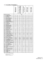
Unit 1.5”
Bracket
2.0”
Bracket
Lazer Z AS 60” Units, All
1
1
1
Lazer Z 60” Units,
SN 600,000 and Lower
1
1
1
Lazer Z 60” Units,
SN 600,000 and Higher
Except AS
2
Lazer Z 66” Units,
2
Lazer Z 72” Units
2
Lazer Z XP 60” Units
2
Lazer Z XP 72” Units
2
Lazer Z XS 60” Units
2
Lazer Z XS 66” Units,
2
Lazer Z XS 72” Units
2
1
1.5” bracket is included in Ultra Vac completion
kit 109-1179 or 109-1189.
2. Install the removable weight assemblies over
the caster arms. On some 60” units one
weight has a wide mounting bracket and one
has a narrow bracket. They will only fit the
machine one way. Weights for all other units
are interchangeable left and right.
3. Install a clevis pin (Item 19) and hairpin (Item
20) on each caster weight to retain them.
4. Tighten knob on weight assembly until the
weight is clamped securely to the caster arm.
Align template along
these 3 edges.


