background image

3005831-2019-04-01.fm

Mechanical assembly


17/64


3.2.3 Baffel plate

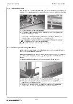
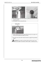
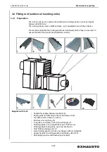
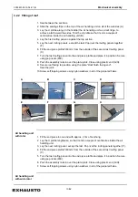
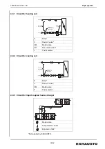
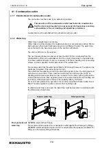
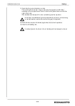
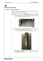
For fans with free outflow without duct connection, fit baffel plate on the outflow ends.
Keep the baffel plate at the correct distance using 6 or 8 braces. 

1. Bend the braces in the square holes so that they align with the holes in the baffel 

plate.

2. Remove the loose fitted flange.
3. Fit the braces on the flange using the supplied countersunk bolts.
4. Fit the baffel plate on the braces.
5. Fit the flange with the baffel plate on the air handling unit again.

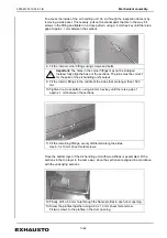
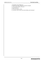
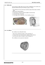
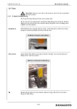
3.2.4 Air diffuser

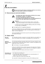
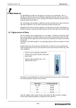
The air diffuser must be fitted after the fan.

1. Remove the loose fitted end panel on the air handling unit.
2. Fit the air diffuser to the panel using the supplied countersunk bolts.
3. Re-fit the panel with the air diffuser to the air handling unit.

The air diffuser must be supported or suspended.

Содержание VEX5000 Series

Страница 1: ...0 Langeskov Denmark Tel 45 65 66 12 34 Fax 45 65 66 11 10 exhausto exhausto dk www exhausto dk 3005831 2019 04 01 fm VEX5000 Assembly installation and maintenance instructions Original instructions VE...

Страница 2: ...plate 17 3 2 4 Air diffuser 17 3 3 Fans 18 3 3 1 Transport safety fitting 18 3 4 Handles on doors 20 3 5 Duct connections 20 3 5 1 Flexible connections 20 3 5 2 ZerAx fans 20 3 6 Filter monitor optio...

Страница 3: ...ections EXcon control system 10 1 Control system component names 35 10 2 Connection diagrams 37 10 2 1 Terminal block 37 10 2 2 Rotary heat exchangers 38 10 2 3 Crossflow heat exchangers 44 10 2 4 Liq...

Страница 4: ...safety and the safety of others and to protect the equipment and ensure its correct operation EXHAUSTO A S accepts no liability for accidents caused by the product not being used in accordance with t...

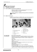
Страница 5: ...ing unit K factor m3 h Filter type Information in connection with ECO design only on information plate for fan sections Code on the information plate The section contains IL Inflow OL Outflow SP Empty...

Страница 6: ...1 2 Unit configurations VEX5000 air handling units are designed as single or two string air handling units and are divided into the following main groups Heating and ventilation Heat recovery Air con...

Страница 7: ...g the air handling unit to the base A number of adjustable screws 5 and fitting for alignment The base is enclosed in packaging on a small pallet Plastic covers Corner covers 8 and plugs 9 for coverin...

Страница 8: ...rol the control system CD for LonWorks 2 1 3 Weight The air handling unit s total weight and dimensions and weight and dimensions of the individual sections are stated on the supplied print out from t...

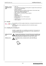
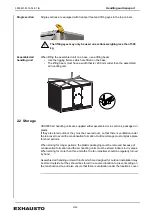
Страница 9: ...aged in plastic If they are stored outdoor they must be covered over so that there is ventilation under the top cover to avoid the condensation formation Outdoor storage must only take place for short...

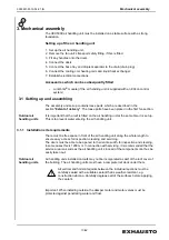
Страница 10: ...r handling unit at the same time it is set up This is to prevent water entering the air handling unit 3 1 1 Installation site requirements There must be free space in front of the air handling unit al...

Страница 11: ...tated on the information plates on the sections 1 Fit a levelling screw under each tab joint 2 Fit and adjust the remaining levelling screws in the holes in the member so that the foundation is levell...

Страница 12: ...plug the holes 6 Stick the sealing strip onto the contact surface along the inner edge on the section before positioning the adjacent section 7 Move the next section onto the base and push it up agai...

Страница 13: ...ng sections 8 Fit the interior corner fittings using screws and bolts Important The holes in the corner fittings may not be enlarged Instead fully align the base or the sections The joins must be corr...

Страница 14: ...ure that all of the panels are positioned correctly Supplied with roof Sealant for sealing between sections 9 Sealing strip for attaching to the air handling unit 9 U profile to form a drain on roof 1...

Страница 15: ...D E 8 Push the assembly rails in over the plate joints Close using plastic end G H 9 Secure roof facing top section using the plate Roof finish facing end Seal the joint 10 Screw self tapping screws u...

Страница 16: ...th the 2 part roofing panel 2 Assemble the 2 part roofing panel using the mounting tab 3 Fit the assembled plates on the rotor 4 Seal the plate joint 5 Fit the four end piece corners 6 Lay the rest of...

Страница 17: ...move the loose fitted flange 3 Fit the braces on the flange using the supplied countersunk bolts 4 Fit the baffel plate on the braces 5 Fit the flange with the baffel plate on the air handling unit ag...

Страница 18: ...Remove the transport safety fitting when the air handling unit is installed in its final location ZerAx fans All ZerAx fans are equipped with two points which lock all four rubber feet during transpo...

Страница 19: ...pressure difference is read as 700 Pa and in the table shown below an ER RH63C fan has a K value of 381 If the unit for airflow is desired to be in l s divide by 3 6 3 5 Example Plenum fan P x K q 700...

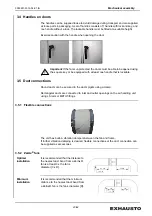
Страница 20: ...ble 3 5 Duct connections Round ducts can be secured to the duct spigots using a clamp Rectangular ducts are connected to inlet and outlet openings on the air handling unit using LS rails or METU fitti...

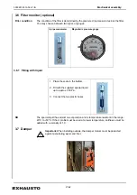
Страница 21: ...uid has almost no evaporation and is temperature resistant in the range 20 C to 50 C If the U profile must be used at a lower temperature antifreeze must be added with a viscosity of 1 0 3 7 Damper Im...

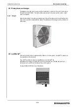
Страница 22: ...and setting up of the air handling unit check that the rotor does not come into contact with the sides The distance to the edge must be uniform on both sides 3 9 LonWorks If the air handling unit is...

Страница 23: ...and around the system Important When installing outside the motor valve must be protected against penetrating water Liquid water glycol is connected to the spigots that run out through the side of the...

Страница 24: ...e VM Motor valve VO Non return valve T Thermometer F Filter V Shut off valve VM Motor valve T Thermometer Motor valve Temperature sensor Expansion tank V T T V V F VM AB A Max 5 m Return Min 60 kPa di...

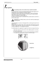
Страница 25: ...where possible make space down in the surface floor It is recommended that the water trap is fitted to its full length however the pipe can be shortened if required if the water trap is too high The...

Страница 26: ...d with It is the responsibility of the electrician to ensure the correct earthing and protection in accordance with the above 5 2 Supply voltage Electrical connection The air handling unit shall be co...

Страница 27: ...lid If the air handling unit is supplied with the EXcon control system the cables are fitted and coiled in the fan section The cables must be run to the control system box in the prepared cable routin...

Страница 28: ...p communication see EXcon instruction manual VEX5000 Control System LonWorks R connection The VEX5000 air handling unit supports communication via a LonWorks connection Note The procedure assumes that...

Страница 29: ...s paper tools or similar 4 Check that the motors are tightened securely 5 Check that the air ducts are fitted on the pressure side of the fans If there is direct access to a fan i e no duct is fitted...

Страница 30: ...nd the free ends of the motor If the vibration level exceeds 11 mm s re balancing must be executed If necessary the vibrations may be checked with the door open but when doing so exercise extreme caut...

Страница 31: ...t up Trin Handling 1 Check for shavings in the bottom of the rotor section Shavings can come from the belt or from the manufacture of the rotor 2 Check that the motor has sufficient distance to the ba...

Страница 32: ...ype and are inserted in holders where they are retained using locking rails The rails push the filter frames against the rubber seal and are released by pushing out the handle on the rails The lifetim...

Страница 33: ...has stopped The run on time for the fans is at least two minutes Even though the air handling unit is equipped with air filters sometimes there can be dust or a covering of dust in the air handling u...

Страница 34: ...0 500 560 500 x 1500 300 x 1500 500 560 700 x 1500 400 x 1500 500 560 630 710 700 x 1800 400 x 1800 560 630 710 900 x 1800 500 x 1800 560 630 710 1200 x 1800 700 x 1800 710 800 1500 x 1800 900 x 1800...

Страница 35: ...ow are found in the web user interface under Service Master Connection EXconMaster NB The subsequent installation of components requires a reconfiguration of the control system and requires another pi...

Страница 36: ...64 Fan IO 1 supply air The figure shown below is found in the web user interface under Service Fan IO Fan IO 1 Connection EXcon Fan IO 1 Fan IO 2 extract air The figure shown below is found in the web...

Страница 37: ...PE L1 L2 L3 N L1 0 0 L2 0 0 L3 0 0 N 0 0 PE 0 0 L1 0 0 L2 0 0 L3 0 0 N 0 0 PE 0 0 PE 0 0 PE 0 0 1 1 1 2 2 2 5 5 5 6 6 6 N N N N N N PE PE PE PE PE PE PE PE PE 8 8 8 7 7 7 9 9 9 10 10 10 11 11 11 12 1...

Страница 38: ...N 24VAC 0VAC 24VAC I O 0VAC I O W1 G G 1 2 3 W2 G G 1 2 3 W5 S W6 S F1 4A 1 2 N N N 5 F4 2 1 4 3 6 5 F5 2 1 4 3 6 5 U1 PE U V W L1 L2 L3 PE U2 PE U V W L1 L2 L3 PE M 3 M2 3x400V M M3 W3 U 1 PE 2 N 3 L...

Страница 39: ...DIN2 6 Din3 7 GND 8 DIN4 9 Din5 10 GND 11 Din6 12 Ain1 13 Ain2 14 GND 15 24VDC 16 Tin1 17 GND 18 Tin2 19 t T6 t T5 11 12 t BT1 t BT2 CO2 G 24V U2 0 10V G0 VAV1 1 24V 2 0 10V 3 VAV2 1 24V 2 0 10V 3 Fi...

Страница 40: ...0VAC I O 0VAC I O 9 7 EXcon MASTER 20 21 Aout1 22 Aout2 23 Aout3 24 25 Dout1 26 27 Dout2 28 29 Dout3 30 31 Dout4 32 33 Dout5 34 35 Dout6 36 37 Dout7 10 1 N 2 N 8 MV3 G 24VAC G0 0VAC Y 0 10V MV4 G 24V...

Страница 41: ...V 55 0V 12 27 24V 18 Din Din 03 01 SF Belimo 1 0V 2 24V Frequency transformer Danfoss FC101 Supply air temperature duct sensor Extract air temperature Motor damper outdoor air spring return ON RS 485...

Страница 42: ...DC W4 SA 1 0V 2 24V 3 24V Exhaust air temp Outdoor air temp Motor damper exhaust air On Off Black Red White RS 485 bus Damper GND 24V on off GND 24V on off GND P1 fan CAV P2 filter P1 fan CAV P2 filte...

Страница 43: ...ectrical connections EXcon control 43 64 Fig 10 2 2 6 Internal connections rotary heat exchangers EXcon master A B C A B C A B C A B Internal bus connections Extract air side Supply air side fire ther...

Страница 44: ...L3 L3 N N PE PE M 3 M1 3x400V T1 2x24VAC 2x60VA 24V 0V 24V 0V L N 24VAC 0VAC 24VAC I O 0VAC I O W1 G G 1 2 3 W2 G G 1 2 3 W5 S W6 S F1 4A 1 2 N N 5 N F4 2 1 4 3 6 5 F5 2 1 4 3 6 5 U1 PE U V W L1 L2 L3...

Страница 45: ...5 DIN2 6 Din3 7 GND 8 DIN4 9 Din5 10 GND 11 Din6 12 Ain1 13 Ain2 14 GND 15 24VDC 16 Tin1 17 GND 18 Tin2 19 t T6 t T5 11 12 t BT1 t BT2 CO2 G 24V U2 0 10V G0 GND VAV1 1 24V 2 0 10V 3 GND VAV2 1 24V 2 0...

Страница 46: ...con MASTER 20 GND 21 Aout1 22 Aout2 23 Aout3 24 25 Dout1 26 27 Dout2 28 29 Dout3 30 31 Dout4 32 33 Dout5 34 35 Dout6 36 37 Dout7 10 1 N 2 N SR1 SR2 Belimo G 24VAC G0 0VAC Y 0 10V 8 MV3 G 24VAC G0 0VAC...

Страница 47: ...1 0 V 2 24 V Supply air temperature duct sensor Extract air temperature Motor damper outdoor air spring return Frequency converter PT 1000 sensor RS 485 Bus P1 fan CAV P2 filter P1 fan CAV P2 filter...

Страница 48: ...SA 1 0V 2 24V 3 24V Exhaust air temperature Outdoor air temperature Motor damper exhaust air On Off Brown White Blue Yellow Green Black Red White PT 1000 f ler DIP switches Frequency converter Damper...

Страница 49: ...cal electrical connections EXcon control 49 64 Fig 10 2 3 6 Internal connections crossflow heat exchangers EXcon master A B C A B C A B C Internal bus connections Supply air side fire thermostats Extr...

Страница 50: ...V 0V L N 24VAC 0VAC 24VAC I O 0VAC I O W1 G G 1 2 3 W2 G G 1 2 3 W5 S W6 S F1 4A 1 2 N N N 5 F4 2 1 4 3 6 5 F5 2 1 4 3 6 5 U1 PE U V W L1 L2 L3 PE U2 PE U V W L1 L2 L3 PE M 3 M2 3x400V Supply air fan...

Страница 51: ...D 5 DIN2 6 Din3 7 GND 8 DIN4 9 Din5 10 GND 11 Din6 12 Ain1 13 Ain2 14 GND 15 24VDC 16 Tin1 17 GND 18 Tin2 19 t T6 t T5 11 12 t BT1 t BT2 CO2 G 24V U2 0 10V G0 VAV1 1 24V 2 0 10V 3 VAV2 1 24V 2 0 10V 3...

Страница 52: ...0VAC I O 0VAC I O 9 7 EXcon MASTER 20 21 Aout1 22 Aout2 23 Aout3 24 25 Dout1 26 27 Dout2 28 29 Dout3 30 31 Dout4 32 33 Dout5 34 35 Dout6 36 37 Dout7 10 1 N 2 N 8 MV3 G 24VAC G0 0VAC Y 0 10V MV4 G 24VA...

Страница 53: ...lter P1 fan CAV P2 filter GND 24V on off GND 24V on off GND Damper Frequency transformer PT 1000 sensor DIP switches Temp 1 GND Temp 2 Supply air temp duct sensor Extract air temp Only for supply air...

Страница 54: ...witches RS 485 bus PT 1000 sensor Temp 1 GND Temp 2 GND 24V on off GND 24V on off GND Damper Frequency converter Fan I O Extract air P1 fan CAV P2 filter P1 fan CAV P2 filter Brown White Red Blue Yell...

Страница 55: ...control 55 64 Fig 10 2 4 6 Internal connections liquid coupled single string EXcon master A B C A B C A B C Fan I O Fan I O Internal bus connections Supply air side fire thermostats Extract air side O...

Страница 56: ...les tableaux de distribution et sch mas VEAB Electric heating coil type CV VEAB Electric heating coil type type VFLPG Alarm_electric heating Alarm_electric heating Alarm_electric heating Alarm_electr...

Страница 57: ...electrical connections EXcon control 57 64 10 2 6 Serial Modbus cable 10 2 7 Rotor control 10 3External connections Fig 10 2 7 1 VEX5010 5100 Fig 10 2 7 2 VEX5130 5200 1 2 5 1 1 2 5 RS485 B RS485 A G...

Страница 58: ...s in case of fire Master Din5 cooling fault Potential free contact which trips in case of fault Cooling pump fault Cooling unit fault Master Din6 external high speed Potential free contact which close...

Страница 59: ...lay Potential free relay 230 VAC 5A Circulation pump for cooling Cooling unit Master Dout3 re circulation relay Damper control Master Dout4 A alarm relay output Potential free relay max 30 V 3 A With...

Страница 60: ...erent air handling unit variants Fig 11 1 Example of an air handling unit with rotary heat exchanger water heating and cooling Fig 11 2 Example of an air handling unit with crossflow heat exchanger wa...

Страница 61: ...ontrol for rotary heat exchanger Variable speed of rotor SA Motor damper exhaust air on off Optional supplied loose fitted in exhaust air duct and closes on standby SF Motor damper outdoor air Supplie...

Страница 62: ...00 N 5 5 mm 1 5 m SSB619 Valve motor IP54 5 to 50 degrees AC 24 V 0 10 V 400 N 5 5 mm SQS65 Water heating coil sensor IP54 incl all tightened return flow ETF 1698 Damper motor inlet 15 Nm spring retur...

Страница 63: ...3005831 2019 04 01 fm Spare parts 63 64...

Страница 64: ......

Отзывы: