background image

SCPI Command Reference

70

IQS-2150

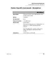
Product-Specific Commands—Description

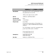
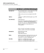
:SOURce[1..n]:POWer:WAVelength

Description

This command selects a wavelength when using 

a dual-wavelength source instrument. 

*RST sets the selected wavelength to the LOW 

value.

Syntax

:SOURce[1..n]:POWer:WAVelength<wsp>UPPe

r|LOWer

Parameter(s)

SelectedSources: 

The program data syntax for the first parameter is 

defined as a <CHARACTER PROGRAM DATA> 

element. The allowed <CHARACTER PROGRAM 

DATA> elements for this parameter are: 

UPPer|LOWer. 

UPPer, switches to the highest wavelength.

LOWer, switches to the lowest wavelength.

Example(s)

SOUR:POW:WAV LOW 

Wait 3 seconds.

SOUR:POW:STAT ON 

Notes

Instrument must be in the Ready state to execute 

this command. This command can cause the 

instrument to enter the Stabilizing state.

See Also

SOURce[1..n]:POWer:WAVelength?

SOURce[1..n]:POWer:WAVelength:LOWer?

SOURce[1..n]:POWer:WAVelength:UPPer?

Содержание IQS-2150

Страница 1: ...User Guide Light Source for IQS Platforms IQS 2150...

Страница 2: ...any infringements of patents or other rights of third parties that may result from its use No license is granted by implication or otherwise under any patent rights of EXFO EXFO s Commerce And Govern...

Страница 3: ...Light Source 17 Selecting a Wavelength 18 Setting the Attenuation 20 Selecting a Modulation Frequency 22 Saving and Recalling Configurations 24 5 Operating Your Light Source 27 Cleaning and Connecting...

Страница 4: ...hnical Support Group 49 Transportation 51 9 Warranty 53 General Information 53 Liability 53 Exclusions 54 Certification 54 Service and Repairs 55 EXFO Service Centers Worldwide 56 A Technical Specific...

Страница 5: ...ndards are designed to provide reasonable protection against harmful interference when the equipment is operated in a commercial environment This equipment generates uses and can radiate radio frequen...

Страница 6: ......

Страница 7: ...gle mode DFB laser emitters in single and dual wavelength configurations for both singlemode and multimode test applications The IQS 2150 Light Source is designed for optimal stability Steady drive ci...

Страница 8: ...into any test system The IQS 2150 Light Source supports local control via the IQS Manager software and remote control through GPIB RS 232 or Ethernet TCP IP using SCPI commands or the provided LabVIEW...

Страница 9: ...proceed unless you understand and meet the required conditions CAUTION Indicates a potentially hazardous situation which if not avoided may result in minor or moderate injury Do not proceed unless you...

Страница 10: ......

Страница 11: ...ein may result in hazardous radiation exposure or impair the protection provided by this unit IMPORTANT When you see the following symbol on your unit make sure that you refer to the instructions prov...

Страница 12: ...Invisible laser radiation may be encountered at the output port The following labels indicate that a product contains a Class 1 source Note The above labels are shown for information purposes only The...

Страница 13: ...g Test Modules CAUTION Never insert or remove a module while the controller unit and its expansion units are turned on This will result in immediate and irreparable damage to both the module and unit...

Страница 14: ...the protective cover from the desired unused module slot 2a Pull the retaining screw knob firmly towards you and release the bottom of the cover 2b Gently pull the top of the protective cover downward...

Страница 15: ...module all the way to the back of the slot until the retaining screw makes contact with the unit casing 6 While applying slight pressure to the module turn the retaining screw knob located at the bot...

Страница 16: ...can insert IQ modules into your controller or expansion unit the IQS Manager software will recognize them However the IQS 600 locking mechanism retaining screw will not work for IQ modules To remove...

Страница 17: ...into the upper grooves of the unit 3b Snap the cover into place by pushing the retaining screw knob CAUTION Pulling out a module by a connector could seriously damage both the module and connector Alw...

Страница 18: ...Manager application available only in IQS Manager 4 0 or later Note For details about IQS Manager refer to the IQS platform user guide To start the application 1 From the Current Modules function tab...

Страница 19: ...h to the module application The laser emission will not be activated Note To start the corresponding monitor window at the same time click Start App Monitor The window opens on the Monitors function t...

Страница 20: ...he main window identifies the operational status of the IQS 2150 Light Source For more information about automating or remotely controlling the IQS 2150 Light Source refer to your platform user guide...

Страница 21: ...hown see figure below Exiting the Application Closing any application that is not currently being used helps freeing system memory To close the application from the main window Click in the top right...

Страница 22: ......

Страница 23: ...re conventions The source is controlled and operated from within the Control Center Depending on your source model some or all of the following operations are available selecting wavelength for dual w...

Страница 24: ...e 18 IQS 2150 Selecting a Wavelength Selecting a Wavelength If you are using a dual wavelength module you can select a wavelength to perform your tests When the source is activated the wavelength appe...

Страница 25: ...ct a wavelength you will see the message Stabilization in progress on the data display until this new wavelength is active Once the stabilization is complete the selected wavelength is displayed on sc...

Страница 26: ...have selected a wavelength if the source is activated To set the source attenuation 1 Select the Instrument function tab 2 Adjust the attenuation of the laser signal emitted by the source from the Att...

Страница 27: ...r to indicate that the change has been applied to the source when it is active The focus indicator rectangle on the control turns blue when setting the attenuation value The attenuation value indicato...

Страница 28: ...of modulation frequencies are available The modulation can be set to different values to better suit your testing needs When the modulation is set to dither it activates the dither mode so the IQS 215...

Страница 29: ...requency To indicate a successful selection Stabilization in progress appears in the data display only if the source is an active laser The Modulation value indicator in the data display indicates the...

Страница 30: ...include all parameters set in the Control Center Instrument function tab and in the Settings function tab if present To save a configuration 1 Select the Configuration function tab 2 In the Current Mo...

Страница 31: ...file you wish to recall and confirm your action You are returned to the application and the new parameters are set To revert to factory settings 1 Select the Configuration function tab 2 Click the Res...

Страница 32: ......

Страница 33: ...it to the port If the fiber is dirty clean it as explained below 2 Clean the fiber ends as follows 2a Gently wipe the fiber end with a lint free swab dipped in isopropyl alcohol 2b Use compressed air...

Страница 34: ...te contact If your connector features a screwsleeve tighten the connector enough to firmly maintain the fiber in place Do not overtighten as this will damage the fiber and the port Note If your fiber...

Страница 35: ...ates that it is for APC type connectors To install an EUI connector adapter onto the EUI baseplate 1 Hold the EUI connector adapter so the dust cap opens downwards 2 Close the dust cap in order to hol...

Страница 36: ...tivating Light Emission Before activating the source read carefully Safety Information on page 5 Upon source activation the set parameter values are used Therefore make sure the source setup is correc...

Страница 37: ...urns off indicating that the source is off The status indicator on the data display is dimmed and the two red arrows disappear from the data display indicating that the source has been deactivated Not...

Страница 38: ......

Страница 39: ...Manager Using Monitor Windows Monitor windows display basic data about modules A combination of resizable windows allows you to create an integrated data display refer to the platform user guide From...

Страница 40: ...ach module you want to monitor If you want to monitor all the modules in the current unit click Select All Monitors If you want to clear your choices click Deselect All Monitors 3 Click Start Monitor...

Страница 41: ...Monitoring Light Source Modules Light Source 35 Using Monitor Windows Rearrange Monitors button 1 or 2 columns Close All button Remove Monitor button Monitor window arrow buttons...

Страница 42: ...or window is selected from the Monitors function tab and is currently active To start QuickTools 1 From the Monitors function tab select the monitor window of the module you wish to control 2 Using th...

Страница 43: ...he Attenuation section you can set the attenuation by clicking the selection arrows on both sides of the list to increase or lower the attenuation The current Attenuation value is displayed between th...

Страница 44: ...panel is not displayed From the Modulation section select a modulation frequency by clicking the selection arrows on both sides of the list for details see Selecting a Modulation Frequency on page 22...

Страница 45: ...p the unit out of direct sunlight Avoid high humidity or significant temperature fluctuations Avoid unnecessary shocks and vibrations If any liquids are spilled on or into the unit turn off the power...

Страница 46: ...dry lint free wiping cloth gently wipe the same surfaces three times with a rotating movement WARNING Looking into the optical connector while the light source is active WILL result in permanent eye...

Страница 47: ...n the cleaning tip one full turn 9 Continue to turn as you withdraw the cleaning tip 10 Repeat steps 7 to 9 but this time with a dry cleaning tip 2 5 mm tip provided by EXFO Note Make sure you don t t...

Страница 48: ...propyl alcohol alcohol may leave traces if used abundantly 3 Slowly insert the cleaning tip into the EUI adapter until it comes out on the other side a slow clockwise rotating movement may help IMPORT...

Страница 49: ...nd ferrule 6c With a dry lint free wiping cloth gently wipe the same surfaces to ensure that the connector and ferrule are perfectly dry 6d Verify connector surface with a portable fiber optic microsc...

Страница 50: ...f specifications depends on operating conditions For example the calibration validity period can be longer or shorter depending on the intensity of use environmental conditions and unit maintenance as...

Страница 51: ...onths after the calibration date Recommended calibration period one year To ensure that your unit conforms to the published specifications calibration may be carried out at an EXFO service center or d...

Страница 52: ......

Страница 53: ...not on Check AC power cord and turn on the IQS 500 600 Controller or Expansion Unit Module is not properly inserted Turn off the IQS 500 600 Controller or Expansion Unit then remove and reinstall the...

Страница 54: ...Viewing Online Documentation Viewing Online Documentation An online version of the IQS 2150 Light Source user guide is available at all times from the application To access the online user guide Clic...

Страница 55: ...rmation about technical support and for a list of other worldwide locations visit the EXFO Web site at www exfo com If you have comments or suggestions about this user documentation you can send them...

Страница 56: ...cal support contact information can be found in the About function tab Select the Technical Support tab to view phone numbers and active Internet links to EXFO s Technical Support Group Use these link...

Страница 57: ...the unit Transportation damage can occur from improper handling The following steps are recommended to minimize the possibility of damage Pack the unit in its original packing material when shipping...

Страница 58: ......

Страница 59: ...uring the warranty period and found to meet all published specifications EXFO will charge standard calibration fees THIS WARRANTY IS IN LIEU OF ALL OTHER WARRANTIES EXPRESSED IMPLIED OR STATUTORY INCL...

Страница 60: ...s pilot lamps batteries and universal interfaces EUI used with EXFO products are not covered by this warranty This warranty excludes failure resulting from improper use or installation normal wear and...

Страница 61: ...nditions under which it was observed 5 Return the equipment prepaid to the address given to you by support personnel Be sure to write the RMA number on the shipping slip EXFO will refuse and return an...

Страница 62: ...exfo service centers EXFO Headquarters Service Center 400 Godin Avenue Quebec Quebec G1M 2K2 CANADA 1 866 683 0155 USA and Canada Tel 1 418 683 5498 Fax 1 418 683 9224 support exfo com EXFO Europe Se...

Страница 63: ...in x 11 1 8 in Temperature Operating Storage 10 C to 40 C 50 F to 104 F 30 C to 70 C 22 F to 158 F Relative humidity 0 to 95 non condensing LASER SAFETY Class 1 Laser Product and Class 1 LED Product T...

Страница 64: ......

Страница 65: ...y which instrument you want to remotely control You must add the following mnemonic at the beginning of any command or query that you send to an instrument LINStrument LogicalInstrumentPos where Logic...

Страница 66: ...r s P SNUMber 61 SOURce 1 n AM INTernal FREQuency ModulationFreq wsp HZ 62 FREQuency 63 POWer ATTenuation Attenuation wsp DB MAXim um MINimum DEFault 64 ATTenuation MAXimum MINimum DEFault 66 STATe Po...

Страница 67: ...urns a value indicating the serial number of the module Syntax SNUMber Parameter s None Response Syntax SerialNumber Response s SerialNumber The response data syntax for SerialNumber is defined as a S...

Страница 68: ...CW Syntax SOURce 1 n AM INTernal FREQuency wsp ModulationFreq wsp HZ Parameter s ModulationFreq The program data syntax for ModulationFreq is defined as a DECIMAL NUMERIC PROGRAM DATA element followe...

Страница 69: ...ncy to 0 Hz CW Syntax SOURce 1 n AM INTernal FREQuency Parameter s None Response Syntax ModulationFrequency Response s ModulationFrequency The response data syntax for ModulationFrequency is defined a...

Страница 70: ...ion The program data syntax for Attenuation is defined as a numeric_value element followed by an optional SUFFIX PROGRAM DATA element The allowed SUFFIX PROGRAM DATA element is DB The Attenuation spec...

Страница 71: ...t Source 65 Product Specific Commands Description Example s SOUR POW STAT ON SOUR POW ATT 2 Notes Instrument must be in the Ready state to execute this command See Also SOURce 1 n POWer ATTenuation SO...

Страница 72: ...on wsp MA Ximum MINimum DEFault Parameter s Parameter 1 The program data syntax for the first parameter is defined as a CHARACTER PROGRAM DATA element The allowed CHARACTER PROGRAM DATA elements for t...

Страница 73: ...enuation The response data syntax for Attenuation is defined as a NR3 NUMERIC RESPONSE DATA element The Attenuation response is the power attenuation of the source in dB Example s SOUR POW STAT ON SOU...

Страница 74: ...tax SOURce 1 n POWer STATe wsp PowerStat e Parameter s PowerState The program data syntax for PowerState is defined as a Boolean Program Data element The PowerState special forms ON and OFF are accept...

Страница 75: ...l source to OFF Syntax SOURce 1 n POWer STATe Parameter s None Response Syntax PowerState Response s PowerState The response data syntax for PowerState is defined as a NR1 NUMERIC RESPONSE DATA elemen...

Страница 76: ...syntax for the first parameter is defined as a CHARACTER PROGRAM DATA element The allowed CHARACTER PROGRAM DATA elements for this parameter are UPPer LOWer UPPer switches to the highest wavelength L...

Страница 77: ...o the LOW value Syntax SOURce 1 n POWer WAVelength Parameter s None Response Syntax SelectedSources Response s SelectedSources The response data syntax for SelectedSources is defined as a CHARACTER RE...

Страница 78: ...as no effect on this command Syntax SOURce 1 n POWer WAVelength COUNt Parameter s None Response Syntax NbWavelength Response s NbWavelength The response data syntax for NbWavelength is defined as a NR...

Страница 79: ...Response Syntax LowerWavelength Response s LowerWavelength The response data syntax for LowerWavelength is defined as a NR3 NUMERIC RESPONSE DATA element The LowerWavelength response is the lowest so...

Страница 80: ...Velength UPPer Parameter s None Response Syntax UpperWavelength Response s UpperWavelength The response data syntax for UpperWavelength is defined as a NR3 NUMERIC RESPONSE DATA element The UpperWavel...

Страница 81: ...Product Specific Commands Description STATus Description This query returns a value indicating the status of the module READY BUSY etc Syntax Parameter s None Response Syntax Response s Status Exampl...

Страница 82: ......

Страница 83: ...window 38 configuration recall 24 save 24 connectors cleaning 40 42 contact information EXFO 50 conventions safety 3 customer service 50 55 D deactivating the light source 30 dither mode 22 E equipmen...

Страница 84: ...ption 33 opening 34 monitoring modules 33 mounting EUI connector adapter 29 O online user guide 48 opening monitor window 34 operating the light source 27 37 P PDF see online user guide port source 1...

Страница 85: ...3 T technical specifications 57 technical support 49 50 temperature for storage 39 title bar 14 transportation requirements 39 51 U user guide see online user guide V viewing results using light sour...

Страница 86: ...363 2006 X Indicates that this toxic or hazardous substance contained in at least one of the homogeneous materials used for this part is above the limit requirement in SJ T11363 2006 SJ T11363 2006 Pa...

Страница 87: ...MARKING REQUIREMENTS Product Environmental protection use period years Logo This E 2 product EXFO 10 Batterya a a If applicable 5...

Страница 88: ...EXFO ASIA PACIFIC 62 Ubi Road 1 09 01 02 Oxley Bizhub 2 SINGAPORE 408734 Tel 65 6333 8241 Fax 65 6333 8242 EXFO CHINA Beijing Global Trade Center Tower C Room 1207 36 North Third Ring Road East Dongch...

Отзывы: