EGW1-IA3-MB-DF1 – Modbus TCP a DF1 User’s Manual
Exemys
www.exemys.com
Rev. 1
12
2.
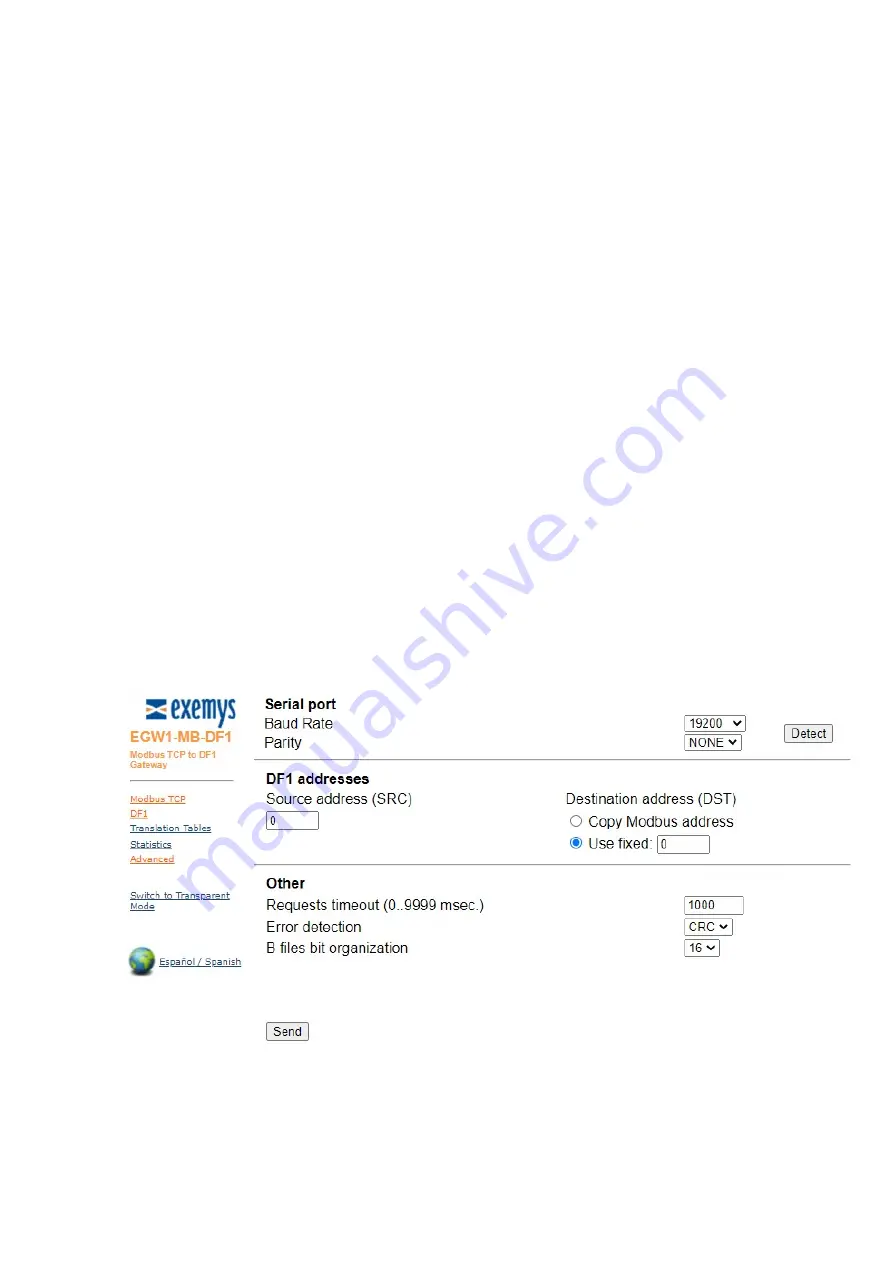
DF1 Source Address: DF1 frames define Source (SRC) and Destination (DST) addresses, corresponding
to the stations that want to exchange data. While these parameters seem to be important, most
implementations do not take care of its values. This is because DF1 is commonly used as a point-to-point
protocol, where only two stations are connected to the wire. As a consequence, addresses are not a
matter. However, there are two associated protocols, called Data Highway (DH) and Data H
(DH+), which provide communication paths among many stations. In these cases, addresses are a must.
This field, as well as the one described below, provide compatibility for those protocols, when interfacing
the EGW1-MB-DF1 with a DH/DH+ network, using an adapter.
3.
DF1 Destination Address: This field defines the Destination Address to be used when issuing DF1
requests. You can choose to use a fixed address, or copy the same address received at the Modbus side.
Again, if running legacy DF1, this field and the one described above do not need to be changed.
4.
Requests Timeout: This timeout defines the round trip time, measured between the incoming request
is removed from the TCP/IP buffer and the appropriate answer is ready to be sent back to the Modbus
TCP master. When the buffering feature is enabled (see TCP buffering in the previous page), the queue
time is not considered a part of this time. This timeout will only run when a new frame is processed. In
other words, when the load is heavy enough to queue frames, you might notice timeouts in the Modbus
TCP master(s), but not exceptions due to time exceeded. Those timeouts are the ones configured at each
master and not the one provided in this field.
5.
Error Checking: Two methods are provided by the DF1 specification to detect frame errors, BCC and
CRC. BCC is a one-octet field appended to a DF1 frame. It contains a checksum of many bytes contained
in the message. By the other hand, the CRC, which stands for Cyclic Redundancy Check and is two-octets
long, is a more robust method in the sense that it will detect more errors than BCC. This setting must be
coherent with that configured in the PLC: if the PLC is set to BCC you have to set EGW1-MB-DF1 to use
BCC and vice versa.


