


Functional characteristics
TIG welding
099-00L200-EW501
13.05.2022
33
5
Functional characteristics
5.1 TIG welding
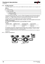
5.1.1 Setting the shielding gas volume (gas test)/rinse hose package
• Slowly open the gas cylinder valve.
• Open the pressure regulator.
• Switch on the power source at the main switch.
• Set the relevant gas quantity for the application on the pressure regulator.
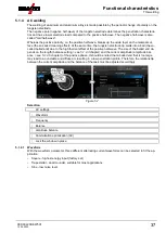
• Press the push-button Gas test / flush hose package to activate the gas test.
Setting the shielding gas quantity (gas test)
• Shielding gas flows for 20 s or until the push-button is pressed again.
Purging long hose packages (purging)
• Press push-button for about 5 s. • Shielding gas flows for approx. 5 min. or until the push-button is
pressed again.
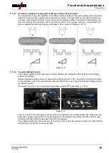
If the shielding gas setting is too low or too high, this can introduce air to the weld pool and may cause
pores to form. Adjust the shielding gas quantity to suit the welding task!
Setting instructions
Welding process
Recommended shielding gas quantity
MAG welding
Wire diameter x 11.5 = l/min
MIG brazing
Wire diameter x 11.5 = l/min
MIG welding (aluminium)
Wire diameter x 13.5 = l/min (100 % argon)
TIG
Gas nozzle diameter in mm corresponds to l/min gas throughput
Helium-rich gas mixtures require a higher gas volume!
The table below can be used to correct the gas volume calculated where necessary:
Shielding gas
Factor
75% Ar/25% He
1.14
50% Ar/50% He
1.35
25% Ar/75% He
1.75
100% He
3.16
For connecting the shielding gas supply and handling the shielding gas cylinder refer to the
power source operating instructions.
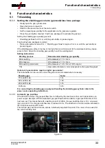
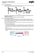
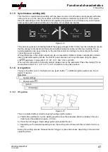
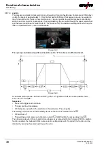
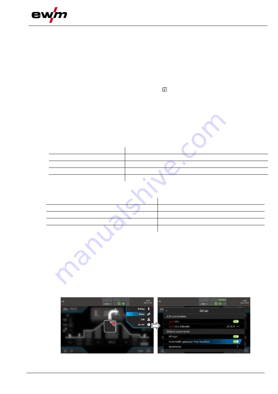
5.1.1.1 Automatic gas post-flow
If the function is active, the gas post-flow time is defined by the machine control unit in dependence on
power output. Example: With the automatic gas post-flow function enabled, a gas post-flow time of 10 s
has been set. This means that with a welding current of 230 A, the gas post-flow time is 10 s. At a weld-
ing current of 115 A, the gas post-flow time is reduced to 5 s. The switched on function will be indicated in
the function sequence with “auto”.
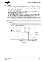
The defined gas post-flow time can also be individually adjusted if required. This value is then saved for
the current welding task.
Figure 5-1


