background image

TECHNICAL REFERENCE MANUAL 

Dyvi 2.0.7.2 


Supervisor 

65 

Video Standard  

The Video Standard can be set when selecting the 

Video Standard


button.  


Note 


The Video Standard setting must be identical for all 
Processing Modules contributing to a Production Cluster 
(those which have the same Cluster-ID). 


GUI and Control Panel are not affected by the video 
standard changes. 

If you want to revert the modifications, use the 

Cancel

 button and 

subsequently use the 

Main Menu

 button. 

Arguments 

Extra parameters for mainframe software can be set by selecting the 

Arguments

 button. 


Warning 

Do not enter any parameters unless instructed to do so by 
EVS Technical Support 

Reference Input 

You can select here 

Analog Ref.

 if the analog reference signal is 

connected to I/O Board or use one of the inputs as reference signal. 

While in the 

Cluster Settings

 menu, parameters changed are marked with 

an asterisk (*) sign and the 

Apply Settings

 button is marked with a yellow 

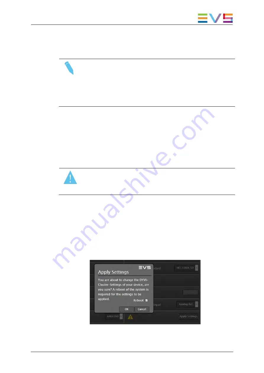
alert. To apply the modified settings, use the 

Apply Settings

 button and 

confirm with 

OK

 in the subsequent dialog box to reboot the system. 


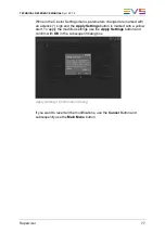
Apply Settings: Confirmation Dialog 

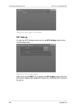
Содержание DYVI

Страница 1: ...HARDWARE TECHNICAL REFERENCE MANUAL Version 2 0 7 2 September 2021 ...

Страница 2: ......

Страница 3: ...ve the quality of the user documentation Do not hesitate to send improvement requests or report any error or inaccuracy on this user manual by e mail to doc evs com Regional Contacts The address and phone number of the EVS headquarters are usually mentioned in the Help About menu in the user interface You will find the full list of addresses and phone numbers of local offices either at the end of ...

Страница 4: ......

Страница 5: ... COMPONENTS AND MODULARITY OVERVIEW 6 4 1 General Description 6 4 2 Processing Module PM 6 4 3 Control Panel CP 7 4 4 Graphical User Interface GUI 8 4 5 Operating Interface 9 5 HARDWARE SPECIFICATIONS 10 5 1 Specifications 10 5 1 1 Processing Module 10 5 1 2 Control Panel v1 1 Desk Inserted Model and Extensions 11 5 1 3 GUI PC 18 5 2 Power Supply 19 5 2 1 Processing Module 19 5 2 2 Control Panels ...

Страница 6: ...upported New PM 36 7 CONTROL PANEL INSTALLATION CABLING AND CONFIGURATION 41 7 1 Control Panel Rear Description 41 7 1 1 Power Supply 41 7 1 2 Ethernet Switch 41 7 1 3 Panel LAN Interface 42 7 1 4 USB Interface 42 7 1 5 Earth Terminal 42 7 2 Control Panel Configuration 43 7 2 1 Changing the Control Panel Background Image 43 8 GUI INSTALLATION AND CONFIGURATION 44 8 1 GUI PC Minimum Requirements 44...

Страница 7: ...3 10 3 2 Network Settings 74 10 3 3 Dyvi Cluster Settings 76 10 3 4 Reset Device 78 10 3 5 Time Settings System Time 79 10 3 6 Software Update 80 10 3 7 Downloading Log Files 82 11 LICENSE MANAGEMENT 83 11 1 Licenses List 83 11 2 XSecure Manager 83 11 3 Requesting the Dyvi Licenses 83 11 3 1 Requesting a Dyvi GUI License 83 11 3 2 Requesting a Dyvi Processing Module License 84 11 4 Installing the ...

Страница 8: ......

Страница 9: ...he sections updated to reflect the new and modified features on Dyvi In this manual the icon has been added in the left margin to highlight information on new and updated features The following new features are available in version 2 0 7 SDI I O Board 2 2 See section 6 3 2 SDI I O Board on page 31 ...

Страница 10: ......

Страница 11: ...Dyvi 2 0 7 2 Dyvi 1 1 Dyvi Welcome to the EVS Dyvi range of products and thank you for using a Dyvi production switcher We will do our best to satisfy your video production needs and we look forward to continuing working with you ...

Страница 12: ...igured hardware components with related software setups Changes or modifications on these devices configuration not expressly approved by the manufacturer could void safe and reliable operation warranty Some elements of the Dyvi switchers are Components Off The Shelf COTS The end user shall not modify the hardware or software configuration of such elements Only manufacturer service people or an au...

Страница 13: ...ions equipment input current 16 A per phase IEC 61000 3 2 2005 A1 2008 A2 2009 German version EN 61000 3 2 2006 A1 2009 A2 2009 DIN EN 61000 4 2 2009 12 VDE 0847 4 2 2009 12 Electromagnetic compatibility EMC Part 4 2 Testing and measurement techniques Electrostatic discharge immunity test IEC 61000 4 2 2008 German version EN 61000 4 2 2009 DIN EN 61000 4 3 2011 04 VDE 0847 4 3 2011 04 Electromagne...

Страница 14: ...61000 4 11 2004 DIN EN 55103 1 2013 11 VDE 0875 103 1 2013 11 Electromagnetic compatibility Product family standard for audio video audio visual and entertainment lighting control apparatus for professional use Part 1 Emissions German version EN 55103 1 2009 A1 2012 DIN EN 55103 2 2010 07 VDE 0875 103 2 2010 07 Electromagnetic compatibility Product family standard for audio video audio visual and ...

Страница 15: ...tlet on a circuit different from that to which the receiver is connected Consult the dealer or an experienced radio TV technician for help 3 4 CE Marking The CE marking is affixed to indicate compliance with the following directives 2004 108 EC of 15 December 2004 on the approximation of the laws of the Member States relating to electromagnetic compatibility and repealing Directive 89 336 Official...

Страница 16: ... a small studio to a major live broadcasting event The Dyvi devices are Processing Module PM Hardkey Control Panel CP Graphical User Interface GUI Each of the devices works electrically independent However for a certain live production multiple of these devices can be configured to contribute to one production entity 4 2 Processing Module PM The processing Module consists of a High performing COTS...

Страница 17: ...x including 4 rows of related OLED displays and two transition sections both consisting of buttons knobs one fader and one touch screen GUI The main Control Panel can be expanded with up to 4 Matrix Extensions each comes with 8 8 control buttons matrix size and related OLED displays Two of those can be mounted at the left side of the basic panel and two at the right The 2 Matrix Extensions at the ...

Страница 18: ... application software It is used to configure live production system setups and provides live monitoring and control support For basic IO Interfaces description dimensions connectors control buttons touch screen environmental parameters of the GUI PC please refer to the manufacturer user guide The Dyvi application special items which differ from the user guide are The installed operating system is...

Страница 19: ...rview 9 4 5 Operating Interface A Dyvi Operating Interface typically consists of 1 Control Panel 1 Graphical User Interface 1 or 2 Multiviewer Screen s optional not provided by EVS fed by the Processing Module s display ports Figure Examples of Dyvi operating interface configuration ...

Страница 20: ...dware Specifications 5 1 Specifications 5 1 1 Processing Module PMY2 5D 3216 Server Specifications CPU dual CPU 2x 12 core with Hyperthreading 2 6GHz RAM 12x 16GB DDR4 2666 PSU redundant hotswap 1600W GPU Quadro P6000 Storage 240GB SSD for OS and 1TB HDD Dimensions 620mm x 444mm x 87mm 2U ...

Страница 21: ...l Panel v1 1 Desk Inserted Model and Extensions Weight Extension Weight 0 9 7 kg 21 lb 1 12 1 kg 26 6 lb 2 14 5 kg 32 lb 3 16 9 kg 37 lb 4 19 3 kg 42 5 lb Table Weight of Desk Inserted Control Panel with a number of extensions mounted Dimensions The following drawings provide the various dimensions in mm ...

Страница 22: ...EVS Broadcast Equipment SA Issue 2 0 7 2 September 2021 12 Hardware Specifications Main Panel Top Main Panel Bottom Main Panel Perspective ...

Страница 23: ...TECHNICAL REFERENCE MANUAL Dyvi 2 0 7 2 Hardware Specifications 13 Main Panel Right Extension Panel Top Extension Panel Bottom ...

Страница 24: ...EVS Broadcast Equipment SA Issue 2 0 7 2 September 2021 14 Hardware Specifications Extension Panel Perspective Extension Panel Left Extension Panel Right ...

Страница 25: ...TECHNICAL REFERENCE MANUAL Dyvi 2 0 7 2 Hardware Specifications 15 Multi Function Module Top Multi Function Module Bottom ...

Страница 26: ...EVS Broadcast Equipment SA Issue 2 0 7 2 September 2021 16 Hardware Specifications Multi Function Module Perspective Multi Function Module Right ...

Страница 27: ...TECHNICAL REFERENCE MANUAL Dyvi 2 0 7 2 Hardware Specifications 17 Cut Out The following drawings provide the various table cut out dimensions in mm Main Panel Extension Panel Multi Function Module ...

Страница 28: ...21 18 Hardware Specifications 5 1 3 GUI PC Dimensions 1 Depth 6 3 cm 2 5 inch 2 Width 57 5 cm 22 7 inch 3 Height 39 3 cm 15 5 inch Weight 7 74 kg 17 03 lbs Note Above figures are valid for Dell OptiPlex 7480 All in One Model of GUI PC is subject to change ...

Страница 29: ...rver unit is properly grounded at all times to avoid electrical shock hazard Grounding always has to be provided through the protective earth pin of the power cable For safe and reliable operation use only the power cables that come with the server system package Electrical Specifications Rated voltage 100 127V Rated frequency 50 60 Hz Power supply max 1000W 100 127V max 1600W 200 240V Input conne...

Страница 30: ...es The secondary hot swappable power supply should be connected to the mains to share the load and to allow automatic power switching to one power supply in case one of the two should fail Weight AHM100PS12 0 5 kg 1 lb Dimensions Dimensions shown in inches mm Electrical Specifications Rated voltage 100 to 240 VAC single phase Rated frequency 50 60 Hz Power supply max 100W 100 240V Input connector ...

Страница 31: ...e building power supply wiring via a non industrial plug and socket outlet or a non industrial appliance coupler or both Correct mains polarity must always be observed Do not use reversible power plugs with this equipment Electrical Consumption Electrical specifications for the Control Panel with 4 extensions Data Type Voltage Value Maximal current full load 100 240 V 1 2 0 6 A ...

Страница 32: ...gh AC range Note Above figures are valid for Dell OptiPlex 7480 All in One Model of GUI PC is subject to change 5 3 Environmental Conditions 5 3 1 Processing Module Operating Temperature 10 35 Relative humidity 20 90 Non Condensing Cooling requirements Forced cooling air flow from front to rear of the server Handling movement Designed for fixed use when in operation Storage and Transport Temperatu...

Страница 33: ...ir flow from the inner panel through a hole at the rear side of the panel Handling movement Designed for fixed use when in operation Storage and Transport Temperature 20 C to 70 C 4 F to 158 F Relative humidity 20 to 90 non condensing 5 3 3 GUI PC Operating Temperature 0 to 35 C 32 to 95 F Relative humidity 20 to 80 non condensing at ambient Storage and Transport Temperature 40 to 65 C 40 to 149 F...

Страница 34: ...ted close to the Processing Module that might increase the Processing Modules environmental temperature Warning Remember that fans are used to air cool the equipment and protect it from overheating Do not block fans intakes during operations Having regard to the weight of the processing module chassis support guides are required for this unit into the rack mount The front ears of the unit are not ...

Страница 35: ... permanent storage HDD2 6 2 2 Front Control Panel Front Control Panel Functions Power Button This is a toggle button If power is connected to the rear power supplies the Power ON LED is off Pushing the power button boots up the system and lights the button Pushing the Power button while the system is running the Processing Module starts the power down process Reset Button Pushing this button resta...

Страница 36: ...0 7 2 September 2021 26 Processing Module Installation and Cabling Front Control Panel Functions LAN 1 LED LAN 2 LED Activity LEDs for the LAN 1 and LAN 2 channel SSD OS Activity LED Indicates Read or Write activities to hard disk drive ...

Страница 37: ... 16 OUT 6 3 1 Standard Backplane Interfaces Motherboard and Power Supply Details Power Supplies Power Cord Connector Power LED The Processing Module has two redundant power supplies Before booting up the system ensure both power supplies are fed with appropriate supply voltage and power cords If power is applied the power LED of each power supply lights up YELLOW If the system is turned on both LE...

Страница 38: ... networks The Full Dyvi Native control is possible on both LAN ports if the connection e g GUI or CP is connected to the Main Unit If a connection is established to an Extension Unit you can operate the menus but you cannot handle Production load save operation limited by the GUI LINK LEDs Each of the 1 GigE ports has 2 LEDs ACT LINK left side OFF No Link ON Linked Blinking Data Activity Speed Lin...

Страница 39: ...ces Control Panel GUI Dyvi Supervisor web server port 80 Dyvi Mobile Webpage macro web server Control Panel port 8090 LinX protocol for EVS XT3 servers control Ember server access port 9000 PixTally port 6669 OCF PixCom port 3456 Ross Xpression Ross Talk Intelligent Interface II Generic Telnet MOXA serial port interface CN 2650 16 2AC VDCP BVW75 protocols EVS Dyvi TALLY BOX tally adaptor based on ...

Страница 40: ...A Issue 2 0 7 2 September 2021 30 Processing Module Installation and Cabling Note IP based protocols Ross Xpression Intelligent Interface are configured by the Dyvi GUI On how to operate Dyvi GUI please refer to the User Manual ...

Страница 41: ...ng Module Installation and Cabling 31 6 3 2 SDI I O Board v2 2 allowing 32 16 per PM Schemas The I O board has 8 inputs and 4 outputs with analog reference Figure SDI I O 8 4 Board Configuration 32 SDI Inputs 16 SDI Output Figure PMY Server Backplane ...

Страница 42: ...t SMPTE 274M SMPTE 296M Tri Level Sync Note The Ref Signal applied must match the system s video reference configuration Connector Type HD BNC Processing Module 32 16 SDI Configuration The Processing Module 32 16 is equipped with 4 SDI IO boards This provides 32 SDI inputs 16 SDI outputs 1 analog output reference Note The Sync Output Located on Card 2 should be connected to the GPU Sync Card The o...

Страница 43: ...ical cable distances distributed productions with direct dark fiber connections and or metropolitan LAN PHY WAVE connections between Main Processing Module and Extension Processing Modules of up to 80 km 50 miles assuming physical signal return latencies of 10 msec 1000 km Note By default analog REF input signal Black Burst or Tri Level Sync is used as video reference source For details on how to ...

Страница 44: ...lay port 1 and the second to display port 2 Order and layout of multiviewers can be changed in Dyvi GUI Note The DVI D port and the display port connectors 3 4 are not used in the Dyvi application The cables adapters converters and screens must be 1080p capable Be careful when using old cables that may be 1080i capable only Some DP and HDMI devices are HDCP protected They may not display the Multi...

Страница 45: ...ication From the Status LEDs only the right bottom one is used in the Dyvi application It indicates the following Note The Display Monitors connected to the display ports have to support progressive video standards e g 1920 1080p even if the reference video standard is interlaced e g 1920 1080i To be an advantage to the low system latency at display port any field interpolation mode on the multivi...

Страница 46: ...r distances of 100 150 meters can be reached using HDMI SDI HDMI converters in between For more details please contact your EVS Technical Support 6 3 4 Network Card Supported New PM Overview Figure Network option with two 100 Gigabit Ethernet Ports QSFP28 The 100 GigE Interfaces are used to interconnect multiple Processing Modules There are different ways to build up those configurations in HW dep...

Страница 47: ... one link between the two A ports Depending on the required cable length it could be a Twinax passive cable or a QSFP28 optical module solution Figure Direct 2 cabling scheme Figure QSFP28 Twinax cable Three Processing Modules stacked local Topology Direct 3 In the topology Direct 3 three Processing Modules are connected with three QSFP28 to QSFP28 cables The cabling depends on the Processing Modu...

Страница 48: ...r details on how to set Device IDs refer to section 11 2 3 Using a Network Switch Topology Switch 100G For more flexible solutions multiple Processing Modules can be connected through a 100 GigE network switch The Switch 100G topology allows to build a production with multiple Processing Modules connected to a switch The QSFP28 port A of each Processing Module must be connected to 100 GigE QSFP28 ...

Страница 49: ...TECHNICAL REFERENCE MANUAL Dyvi 2 0 7 2 Processing Module Installation and Cabling 39 Figure Example of Switch 100G cabling scheme Figure QSFP28 Twinax cable ...

Страница 50: ...ontributing to a Production Cluster those which have the same Cluster ID For proper network settings and validated devices please refer to the limited version of the EVS Network Design Guide For support on network switches and their configuration contact your EVS Technical Support On how to configure Processing Modules to Dyvi Productions please refer to Supervisor section ...

Страница 51: ...er supply inputs to the Control Panel For normal mode one external power supply is needed For redundant power mode two external power supplies are needed To ensure reliable operation only use original power supplies as delivered with Dyvi Control Panel 7 1 2 Ethernet Switch The Control Panel has a built in 5 Port GigE switch each capable of 10 100 1000 Mbps via RJ 45 connector Use Category 5e Cat ...

Страница 52: ...etwork switch Note For safe operation the control connections between Control Panel GUI and Processing Module needs reliable 1 GigE net links 7 1 4 USB Interface There are two USB ports on the rear of the Control Panel The ports can be used for USB devices such as mouse keyboard or USB flash drive 7 1 5 Earth Terminal Normally the separate grounding at the protective earth terminal is not required...

Страница 53: ...lows 1 Save the new image file as custom png 2 Copy the custom png file to the root directory of an USB key 3 Insert the USB key in the USB port of the Control Panel 4 Perform a software reset of the Control Panel Main Menu Delegate System Reset SW Reset or perform a power cycle 5 When the Control Panel is booting up the old image will still be visible Wait a moment until the image is changed 6 Re...

Страница 54: ...1 GUI PC Minimum Requirements Before installing the Dyvi licensed software you should check that your PC meets the following minimum requirements CPU 15 core RAM 16GB Storage Class 35 SSD 256GB OS Windows 10 64bit 8 2 Installation The GUI application comes as a compressed file 1 Use the Windows Explorer to copy the software file from the distribution media to the GUI 2 Run the setup file DYVI GUI_...

Страница 55: ...AL Dyvi 2 0 7 2 GUI Installation and Configuration 45 5 Select the destination folder e g C Program Files DYVI GUI 6 Confirm the full installation with Next 7 Select additional tasks for the installation wizard and click Next ...

Страница 56: ...EVS Broadcast Equipment SA Issue 2 0 7 2 September 2021 46 GUI Installation and Configuration ...

Страница 57: ...NICAL REFERENCE MANUAL Dyvi 2 0 7 2 GUI Installation and Configuration 47 8 Click on Install to start the installation 9 Wait until the installation process is done 10 Click Finish to exit the installation ...

Страница 58: ... Dyvi system is delivered Network setting is required for instance when a customer wants to change the IP address To access the network settings proceed as follows 1 Right click the Network icon on the desktop and choose Properties 2 Click the option Change Adapter Settings in the top left corner of the dialog box 3 Right click the Ethernet adaptor and choose Properties ...

Страница 59: ... 0 7 2 GUI Installation and Configuration 49 4 Select Internet Protocol Version 4 TCP IPv4 and click on Properties 5 Change Verify the Network Settings o IP address o Subnet mask o Default gateway 6 Validate your changes by clicking OK ...

Страница 60: ...nerated automatically out of the last byte of the Device s IP address plus adding an offset of 1000 In the above example the IP address low byte was 92 which results in a Device ID of 1092 decimal 8 4 Reset Device To reset or shut down the GUI proceed as follows 1 Click the Windows Start button 2 Select the Power button 3 Select the Restart or Shutdown function 8 5 Launch the Dyvi GUI To launch th...

Страница 61: ...s To download the log files generated by the GUI proceed as follows 1 Close or minimize the GUI software 2 Open the Windows Explorer and browse for the following directory C Program Files DYVI GUI 3 Right click the log folder and select 7 Zip Add to log zip 4 Send the log zip file to the EVS support service ...

Страница 62: ...connection to the Dyvi Panel s GUI and then third party devices such as the XT and or other servers and systems 9 3 PM Network High speed network The Internal PM Network is dedicated for the Internal distribution of live streams amongst all the Processing Modules connected together within what we call a Cluster This Cluster network could be spread across one Building Country Nation or Planet and i...

Страница 63: ...me Settings Resetting the device Log File Access The password to log into the Supervisor is dyvilive The GUI does not have a supervisor implementation yet The Supervisor GUI subsection describes alternative ways to access the related settings Network Configuration The Dyvi factory network addresses are CP 100 10 1 90 PM 100 10 1 91 GUI 100 10 1 92 Configuring a new Dyvi System starts with connecti...

Страница 64: ...ible on those other devices in case of they should be selected on the left side of the Main Window 10 2 Processing Module 10 2 1 Managing the Network To manage the network on a Dyvi Processing Module proceed as follows 1 Establish a network connection between your browsing Device and one the first Dyvi Processing Module s LAN1 connector 2 Open the Browser Mozilla Firefox preferred or MS Internet E...

Страница 65: ...ress The right side shows the Processing Module s relevant preset summary Note Changing configuration with the Supervisor as described below often results in a reboot of the connected system to activate the new settings When the browser communication is back a manual refresh of the browser window has to be executed by pressing the F5 key to ensure the browser does not show up obsolete cached windo...

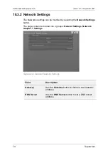
Страница 66: ...ettings button in the Devices menu The page content is divided into 3 groups General Settings Network Adapter 1 Settings and Network Adapter 2 Settings Supervisor Network Settings General Settings General Settings Field Description Gateway Use the Gateway button to define a new gateway address DNS Server Use the DNS Server button to set a DNS server address ...

Страница 67: ...ings Field Description IP Address Use the IP Address button to set a unique IP address from the same range with Dyvi Control Panel and GUI This port is used to connect Dyvi Control Panel GUI and external IP controlled devices Netmask Use the Netmask button to modify the netmask Supervisor Network Settings Network Adapter 2 Settings ...

Страница 68: ...e Netmask button to modify the netmask Note The Network Adapter 2 does not support a Gateway Note For common rules on how to set network parameters please contact your network administrator or contact EVS Technical Support While in the Devices menu parameters changed are marked with an asterisk sign and the Apply Settings button is marked with a yellow alert To apply the modified settings use the ...

Страница 69: ...Note The video input output standards supported for multi PM configurations are the following 1080i50 1080i59 720p50 720p59 Device ID The Device ID enumerates the Processing Modules of a cluster starting with Device ID 1 Device ID 1 has a special meaning in a Dyvi Production since it is the Main Processing Module which is downstream to all the others PMs which are so called Extension Processing Mo...

Страница 70: ...ber of Processing Modules connected to the network The following table presents the currently supported topologies Topology Comment None The Processing Module is a standalone module and not connected to the network Direct 2 2 Processing Modules are directly wired Direct 3 3 Processing Modules are directly wired Switch 100G Multiple Processing Modules are linked via 100GbE switch Note Each Topology...

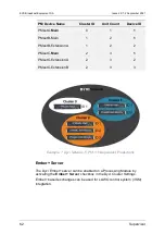
Страница 71: ...wing tables provide examples of rearranging 6 Processing Modules for 2 and 3 independent productions at one Dyvi network PM Device Name Cluster ID Unit Count Device ID PMsetA Main 0 3 1 PMsetA ExtensionA 0 3 2 PMsetA ExtensionB 0 3 3 PMsetB Main 1 3 1 PMsetB ExtensionA 1 3 2 PMsetB ExtensionB 1 3 3 Example 1 Dyvi Network 6 PM 2 Independent Productions ...

Страница 72: ...setB ExtensionA 1 2 2 PMsetC Main 2 3 1 PMsetC ExtensionA 2 3 2 PMsetC ExtensionB 2 3 3 Example 1 Dyvi Network 6 PM 3 Independent Productions Ember Server The Dyvi Ember server can be enabled on a Processing Module by activating the Ember Server checkbox in the Dyvi Cluster Settings Ember based exchanges can be used for LAWO control system VSM integration ...

Страница 73: ... Reducing the size of Low Res Scale might be an effective way of fitting data to 10Gbit network Error Reference source not found topology Note The Low Res Scale setting must be identical for all Processing Modules contributing to a Production Cluster those which have the same Cluster ID Low Latency Mode o Low Latency Mode is a solution for 1 PM productions running in interlaced mode 1080i50 or 108...

Страница 74: ...an be selected from the drop down menu Options available are 8 bit and 16 bit This menu option changes the color depth of processing video by GPU only The default mode is 16 bit Switching to 8 bit can optimize your GPU load and this compromise may be noticed in moderate quality of gradients on CRT monitors Note I O boards and CPU are not affected by GPU Processing mode changes GUI and Control Pane...

Страница 75: ...enu button Arguments Extra parameters for mainframe software can be set by selecting the Arguments button Warning Do not enter any parameters unless instructed to do so by EVS Technical Support Reference Input You can select here Analog Ref if the analog reference signal is connected to I O Board or use one of the inputs as reference signal While in the Cluster Settings menu parameters changed are...

Страница 76: ...set a device proceed as follows 1 Ensure the correct device you want to reset is labeled at the headline of the menu 2 Press and hold the SHIFT key to enable the Reset and Shutdown controls 3 Select the Reset or Shutdown control you want to execute Warning Selecting one of the Reset or Shutdown buttons will have immediate effect on the Production Avoid pushing these buttons while On Air except of ...

Страница 77: ...or Time Settings window System Time To enter the System Time window select the System Time button in the Time Settings menu Press and hold the SHIFT key to enable the System Time button Use the Apply button to take over the new time and date values of the Dyvi device identified in the Headline of the System Time menu Note The System Time menu is disable when NTP server is enabled in the NTP Settin...

Страница 78: ...me window NTP Settings To enter the NTP Settings window select the NTP Settings button in the Time Settings menu Supervisor NTP Server window Press and hold the SHIFT key to enable the NTP Setting button Enter the NTP server address and enable NTP function to confirm the NTP mode for the device ...

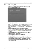
Страница 79: ...lecting the Software Update button in the Devices menu Supervisor Software Update On the Processing Module there are two disk partitions Partition 1 Partition 2 Each of the partitions holds a complete and independent set of Dyvi Processing Module software The partitions can be used to hold a backup version software or to have different version for test and evaluation purposes ...

Страница 80: ...gz Use the Install Software control and agree to the subsequent dialog to start the software installation process If the installation process is completed the next Processing Module Reset swaps automatically to the newly installed version Note Note that the first reboot might take longer than the expected 1 minute Note After software installation and reconnection of the GUI to the system the GUI m...

Страница 81: ...use this would stop the software installation procedure and result in an incomplete installation 10 2 7 Downloading Log Files To download the log files of the appropriate device proceed as follows 1 In the Devices Overview window select the appropriate device 2 Press and hold down the SHIFT key and click the Log button to enter the Log menu 3 Click on the Dyvi Logs symbol in order to download the ...

Страница 82: ...e Shift key and click the Ping button The remote IP address can be the IP address of another Processing Module or of an external device Click the Remote Ip button to check if the Processing Module hosting the Supervisor in the example 10 143 137 32 can reach the other device When the Local Ip field is empty your local default IP address is used If you have more network adapters active you can spec...

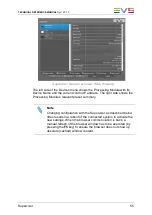
Страница 83: ...ork address e g http 100 10 1 90 3 Enter the password to log into the Supervisor dyvilive The connection will open the Devices Overview window of the Supervisor Supervisor Devices Overview window The left side of the Devices Overview shows the Control Panel with its Device Name and the current control IP address The right side shows the Control Panel s preset summary Note Changing the configuratio...

Страница 84: ... be modified by selecting the Network Settings button The page content is divided into 2 groups General Settings Network Adapter 1 Settings Supervisor General Network Settings Field Description Gateway Use the Gateway button to define a new gateway address DNS Server Use the DNS Server button to set a DNS server address ...

Страница 85: ...tmask Note For common rules on how to set network parameters please contact your network administrator or contact EVS Technical Support While in the Devices menu parameters changed are marked with an asterisk sign and the Apply Settings button is marked with a yellow alert To apply the modified settings use the Apply Settings button and confirm with OK in the subsequent dialog box Network Settings...

Страница 86: ...ings button Supervisor Dyvi Cluster Settings Device ID The Device ID enumerates all Control Panels of all clusters at a Dyvi network starting for example with Device ID 500 Device Name For the end users convenience the Device Name should be a unique logical name The following table provides an example for with 3 Control Panels at one Dyvi network CP Device Name Cluster ID Unit Count Device ID Ctrl...

Страница 87: ... asterisk sign and the Apply Settings button is marked with a yellow alert To apply the modified settings use the Apply Settings button and confirm with OK in the subsequent dialog box Apply Settings Confirmation Dialog If you want to revert all the modifications use the Cancel Button and subsequently use the Main Menu button ...

Страница 88: ...ice proceed as follows 1 Ensure the correct device you want to reset is labeled at the headline of the menu 2 Press and hold the SHIFT key to enable the Reset and Shutdown controls 3 Select the Reset or Shutdown control you want to execute Warning Selecting one of the Reset or Shutdown buttons will have immediate effect on the Production Avoid pushing these buttons while On Air except in operation...

Страница 89: ...Devices menu Supervisor Time Settings Dialog System Time To enter the System Time window select the System Time button in the Time Settings menu Press and hold the SHIFT key to enable the System Time button Use the Apply button to take over the new time and date values of the Dyvi device identified in the Headline of the Time Settings menu Supervisor Set System Time Dialog ...

Страница 90: ...the following information It shows the software version installed on the two partitions The current active partition is label with a sign In the above example Partition 1 is active It allows to swap the active partition In the above example Partition 2 would become active after the swap It gives installation access to the inactive partition In a first step you have to choose the new version file t...

Страница 91: ...he correct device you want to modify is labeled on the headline of the menu This has to be the device the network browser is connected to Do not close the browser window while the software installation process is in progress because this would stop the software installation procedure and result in an incomplete installation ...

Страница 92: ...follows 1 In the Devices Overview window select the appropriate device 2 Press and hold down the SHIFT key and click the Log button to enter the Log menu 3 Click on the Dyvi Logs symbol in order to download the zipped log file 4 Open your file browser and locate the downloaded file in the Download folder 5 Send the dyviLogs tar gz file to the EVS support service ...

Страница 93: ...ated through the EVS XSecure Manager tool The license for the PMs need to be requested and activated using the Supervisor 11 2 XSecure Manager The XSecure Manager is a tool which allows you to request and activate Dyvi license keys for the GUI The XSecure Manager is installed on the GUI PC 11 3 Requesting the Dyvi Licenses 11 3 1 Requesting a Dyvi GUI License To request a license key for your Dyvi...

Страница 94: ...sing Module License To request a license for a Processing Module proceed as follows 1 Open a web browser e g Internet Explorer 2 Connect to the Dyvi Processing Module using the device network address e g 100 10 1 91 3 The browser will open the Devices Overview window of the Supervisor 4 Enter the following password to log into the Supervisor dyvilive ...

Страница 95: ...TECHNICAL REFERENCE MANUAL Dyvi 2 0 7 2 License Management 85 5 Open the DYVI License menu 6 Click Download System Info and save the request XML file 7 Repeat the steps for all Processing Modules ...

Страница 96: ...select the obtained XML file and confirm with Open 3 A message notifies you that the license was successfully installed Confirm with OK You will see the installed license within the XSecure Manager 11 4 2 Installing the Dyvi Processing Module License To install the license for a Dyvi Processing Module proceed as follows 1 Open the web browser and connect to the processing module in order to get ac...

Страница 97: ...install the license file 5 Confirm with OK to install the license The system will restart the software afterwards A message notifies you that the license was successfully installed Confirm with OK When refreshing the Supervisor website you will see the installed license within the DYVI License menu 6 Repeat those steps for all processing modules ...

Страница 98: ...ation 12 External Device Configuration Please refer to separate documentation on the EVS Download area for information on External Device configuration including the following Tally Interfaces LAWO VSM BFE MOXA PIX Tally Interface VSM Studio VSM Label Transfer VSM Tally Configuration ...

Страница 99: ...HNICAL REFERENCE MANUAL Dyvi 2 0 7 2 Dyvi Contact Information 89 13 Dyvi Contact Information Technical Support EVS Technical Support http myservices evs com Sales EVS Sales Contact http www evs com contact ...

Страница 100: ...rective Scalable Video Systems EVS Broadcast Equipment SA will be responsible for all costs associated with recycling and disposal However the last owner is responsible for removing packing and sending the equipment to EVS Broadcast Equipment SA Mina Rees Straße 8 64295 Darmstadt Germany For further information of the Dyvi take back system please refer to Dyvi Technical Support ...

Страница 101: ......

Страница 102: ......

Отзывы: