Evolution FURY 52551 Скачать руководство пользователя страница 19

19

www.evolutionfury.com

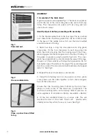
6. Anti-bounce Device

If required, when cutting thin sheet or thin walled box-
section material 

(maximum 3mm thickness applies when 

Steel cutting),

 the anti-bounce device can be employed. 

See Fig 24. Adjust using the adjustable handle and knob for 
best position.

Note

Adjust the anti-bounce device so that the head does not quite 
touch the material to be cut. You can achieve this by gently 
clamping the material to be cut with the anti-bounce device, 
and then backing off the head by 1/4 to1/2 a turn.

BASIC TABLE SAW OPERATIONS
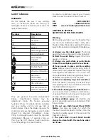
WARNING

Never attempt freehand cuts on this machine. Always use 
the appropriate guide or fence to minimise the possibility 
of the blade binding and kickback. We recommend that 
the saw blade protrudes through the material to be cut by 
approximately 3mm.  Adjust the height of the blade as 
previously described. This machine is not suitable for cutting 
rebates or stopped grooves. A vacuum cleaner or workshop 
dust extraction device can be connected to the extraction port 
found at the rear of the machine if required. See Fig 25.

Note:

 Adjust the blade guard for mitre, bevel or compound 

cutting as detailed in Assembly 8.

1. Crosscutting

Set the mitre gauge to 0

0

 and tighten using the vertical handle. 

Position in the desired ‘T’ slot and adjust the mitre face plate as 
previously described. Index the material to be cut against the 
mitre gauge faceplate. Switch on the saw and allow to reach 
full operating speed before making your cut. See Fig 26.

Note:

 Adjust the blade guard for mitre, bevel or compound 

cutting as detailed in Assembly 8.

2. Mitre crosscutting

Mitre crosscutting is cutting the material at an angle other 
than 90

0

. Set the mitre gauge to the desired angle, tighten and 

proceed as crosscutting above.

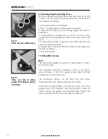
3. Bevel crosscutting

Bevel crosscutting is the same as crosscutting but with the 
blade tilted at an angle. Tilt the blade to the desired angle as 
previously described, and ensure that it is locked in place. Set 
the mitre gauge to 0

0

 and adjust the faceplate so that it does 

not touch or foul the saw blade as it passes. Index the material 
against the mitre gauge and make your cut. See Fig 27.

Fig 25
Close up view of vacuum 
cleaner attached to outlet 
port.

Fig 24
Close up of mitre gauge. 
Anti-bounce device fitted.

Fig 26
View of machine set for 
Crosscutting.

Fig 27
View of machine set for 
bevel crosscutting.

Содержание FURY 52551

Страница 1: ...255mm TCT Multipurpose Table Saw Original Instructions Read instructions before operating this tool www evolutionfury com...

Страница 2: ...onformity 04 Important Information 05 12 Month Limited Warranty 05 General Safety Rules 05 Safety Precautions for Table Saws 07 Symbols 08 Additional Specific Safety Rules 08 Specification 09 Machine...

Страница 3: ...ectives 2006 42 EC Machine Directive 2006 95 EC Low Voltage Directive 2004 108 EC EMC Directive 2002 95 EC Restriction of the use of Certain Hazardous Substances in Electrical and Electric equipment T...

Страница 4: ...m There is no warranty written or verbal for saw blades In no event shall Evolution Power Tools be liable for loss or damage resulting directly or indirectly from the use of our merchandise or from an...

Страница 5: ...e before servicing and when changing accessories such as blades bits and cutters disconnect tools from the power supply 16 Remove adjusting keys and wrenches Form the habit of checking to see that key...

Страница 6: ...an and the thickness of the body of the saw blade shall not be more than the thickness of the riving knife d Take care that the selection of the saw blade is suitable for the material to be cut e Wear...

Страница 7: ...r table saw it is important that you read and understand these safety rules Failure to follow these rules could result in serious injury to the operator or damage to the table saw a Always use the bla...

Страница 8: ...hands out of the path of the saw blade r Never reach around the saw blade s Turn off machine and wait for saw blade to stop before making any fence adjustments t Never pull or carry the tool by the po...

Страница 9: ...9 www evolutionfury com KNOW YOUR PARTS 1 Fixings grouped in sets 3 Table extensions and struts etc 2 Stand components 4 Other parts mitre gauge rip fence top guard fence rail...

Страница 10: ...RIP FENCE 6 RIP FENCE LOCKING HANDLE 7 RIP FENCE SCALE MAGNIFIER 8 SLIDING MITRE FENCE 9 ANTI BOUNCE DEVICE 10 RISE FALL ADJUSTMENT HANDLE 11 BEVEL LOCKING LEVER 12 BEVEL ADJUSTMENT WHEEL 13 PUSH STI...

Страница 11: ...s piece using four 6mm hex bolts This cross piece has sloped ends to accommodate the splay of the legs Ensure it is fitted correctly with slope facing upwards Do not fully tighten any of the bolts at...

Страница 12: ...rough the four corner holes in the stand See Fig 5 3 Table Extensions Note The pressed steel table extensions are not handed and can fit on either side of the machine However the single hole in the en...

Страница 13: ...ent of the table extensions is possible by repositioning the relevant fixing screw in their slots 4 Assembling the Rip fence The rip fence guide has an adjustable aluminium faceplate For normal use th...

Страница 14: ...ut the following procedure The Fence Rail needs to be positioned correctly for its scale to read accurately 1 Locate the Rip Fence in the Fence Rail to the RH side of the Blade 2 Raise the saw blade s...

Страница 15: ...d 6 Tighten and re check the Rip Fence when correct alignment has been achieved 7 Lower the blade 7 Sliding Mitre Gauge Note The sliding mitre gauge fits in either of the inverted T slots in the machi...

Страница 16: ...the blade guard Ensure that it is working efficiently and covers the blade entirely at the sides as well as the crown 4 Lower the blade a little and recheck that the blade guard operation 5 When sati...

Страница 17: ...ng and lowering handle is used to raise or lower the blade Turn clockwise to lower the blade and counter clockwise to raise the blade See Fig 19 3 Tilting the Blade The blade can be tilted up to 450 t...

Страница 18: ...re attach the wing nuts See Fig 22 Adjust as above Remember to return to the original configuration when the rip fence is in the normal RH operating position 5 Mitre Gauge The mitre gauge can be used...

Страница 19: ...djust the blade guard for mitre bevel or compound cutting as detailed in Assembly 8 1 Crosscutting Set the mitre gauge to 00 and tighten using the vertical handle Position in the desired T slot and ad...

Страница 20: ...tre gauge positioned on the LH side of the machine with the rip fence on the RH side of the machine See Fig 29 The rip fence can be used as a length stop if it is properly set and adjusted Note Align...

Страница 21: ...p fence Use smooth steady pressure and employ a push stick if necessary When the ripping width is greater than 300mm and with care both hands can be used to guide feed the material through the saw The...

Страница 22: ...Replace the outer flange and nut and tighten securely with the spanners provided Check that both blade flanges are in contact with the blade 9 Replace the table access plate and its fixing screws Ens...

Страница 23: ...blades onto the 25 4mm metal flange Secure the blades with the centre hand nut ENVIRONMENTAL PROTECTION Waste electrical products should not be disposed of with household waste Please recycle where fa...

Страница 24: ...24 www evolutionfury com Parts Lists...

Отзывы: