


14
www.evolutionfury.com
5. The Fence Rail
Note
The Fence Rail is supplied in two pieces which slot together.
The metal locating bar should be inserted into the rectangular
voids of the two extrusions to bridge both parts of the fence
rail. The bar should be equally located in either side of the
fence rail. See Fig 10. The six ø6mm x 15mm domed headed
coach bolts should be slid into the channel at the back of the
Fence Rail.
1. Offer the Fence Rail up to the front of the machine.
2. Position the six bolts to align with the six holes (one in each
extension and four in the main aluminium table). See Fig 11
3. Attach the Fence Rail to the machine using washers and
ø6mm nuts. Hand tighten only.
Adjusting
Warning
The machine must not be connected to its mains supply when
carrying out the following procedure.
The Fence Rail needs to be positioned correctly for its
scale to read accurately.
1. Locate the Rip Fence in the Fence Rail to the RH side of
the Blade.
2. Raise the saw blade (see Operation Controls 2)
3. Slide the Rip Fence along the Fence Rail until it rests against
the raised saw blade.
4. Look through the Rip Fence magnifier, and gently move the
Fence Rail to the right or left until the ‘0’ position on the scale
coincides with the datum line in the magnifier. See Fig 12.
5. Check, and when satisfied that calibration has been
achieved, tighten the six Fence Rail nuts securely.
6. Lower the Blade.
Note
The Rip Fence simply slots into the Fence Rail, and can be
locked into position anywhere along the rails length, and at
either side of the machine by pressing the locking lever down.
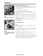
Fig 11
View of fence rail being
attached to machine.
Fig 12
Close up detailed view
of the fence rail being
adjusted.
Fig 10
Close up of view of fence
rail slotted together.
Содержание FURY 52551
Страница 24: ...24 www evolutionfury com Parts Lists...