background image

AC133 

Wall Switch 

Installation Instructions 

The AC133 Wall Switch is a portable wireless switch designed to control the 
ON/OFF  status  of  other  associated  devices  thru  the  Gateway.  After  receiving 
the signals emitted by the Wall Switch, the Gateway can then give commands 
or operate according to its own settings. Its great compatibility with our U-Net 
family  security  products  makes  it  suitable  for  smart  home  cloud  based 
platforms such as Homesys. 

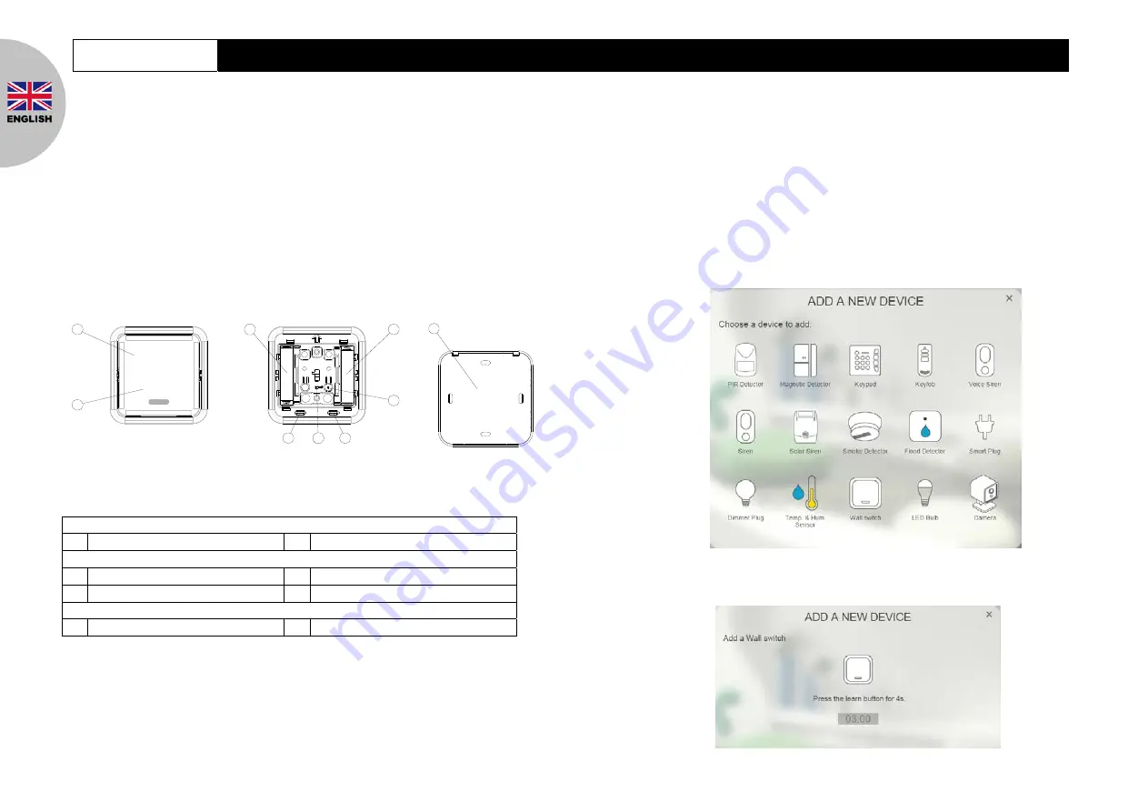
Product Overview 

1

2

3

3

LINK

4

5

5

6

7

Front View 

 OFF 

Knob 

 ON 

Knob 

Inside View 

 Battery 

Compartments 

 Link 

Button 

  Rear Cover Latch 

 LED 

Indicator 

Rear View 

 Rear 

Cover 

Binding with Homesys 

1. Gently lever the bottom edge of the front cover to detach it from the main body.

2. Prepare two 1.5V AAA alkaline batteries. Do not insert them into the unit yet.

3. Log into the Homesys account from a web browser.

4. Select “System”.

5. Select “Add a New Device”, then “Wall Switch”.

6. The following screen will appear. This means the gateway is entering binding mode.

Содержание AC133

Страница 1: ...AC133 e anual Manuale utente...

Страница 2: ...for smart home cloud based platforms such as Homesys Product Overview 1 2 3 3 LINK 4 5 5 6 7 Front View OFF Knob ON Knob Inside View Battery Compartments Link Button Rear Cover Latch LED Indicator Re...

Страница 3: ...Gateway receives the signal If not move closer to the Gateway until the test is successful 5 For the Wall switch to control other devices on the Homesys system a Scenes needs to be created Scenes are...

Страница 4: ...the rear cover on the wall and turn the two screws into the wall or wall plugs DO NOT fasten too tightly as the rear cover might be damaged Then replace the main body and the front cover 60MM Maintena...

Страница 5: ...more than 6 seconds until the LED turns off 4 Remove the batteries and re insert them again If the LED blinks repeatedly once every 30 seconds this implies the device is reset back to factory mode Sp...

Страница 6: ...a serie Homesys Descrizione 1 2 3 3 LINK 4 5 5 7 6 1 2 3 3 LINK 4 5 5 7 6 Vista frontale Interruttore ON Interruttore OFF Vista interna Spazio batterie Tasto di ricerca Aggancio per base Indicatore LE...

Страница 7: ...ntrollare un altro dispositivo Homesys tramite l interruttore necessario creare una scena Una scena una regola personalizzata del sistema Homesys che permette di eseguire una determinata azione ogni v...

Страница 8: ...o necessari iv Posizionare la placca posteriore sulla parete ed inserire le due viti Non avvitare la placca troppo stretta per evitare che si possa danneggiare Applicare quindi il resto dell interrutt...

Страница 9: ...senza preavviso Precauzioni Non gettare dispositivi elettronici come normali rifiuti utilizzare servizi di raccolta differenziata Contattare il proprio comune per informazioni sul tipo di raccolta dif...

Отзывы: