


21
ITEM
DESCRIPTION
1.
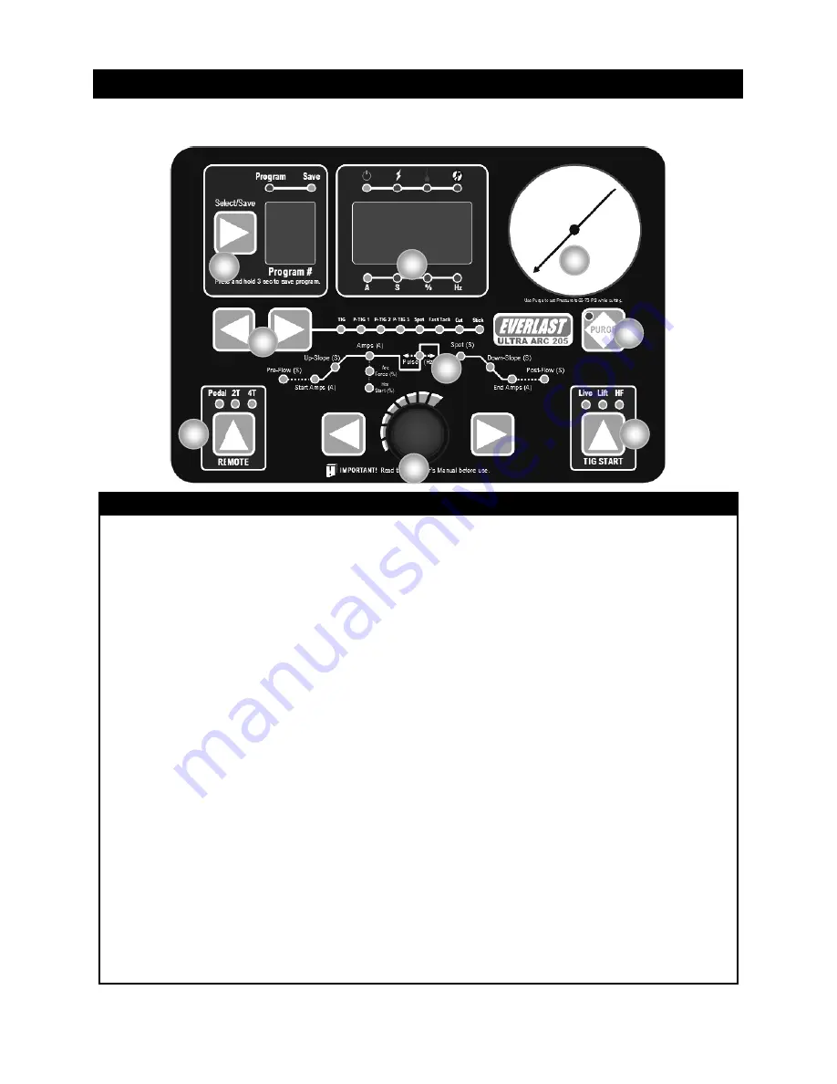
Memory. If you intend to save a program, press select to toggle to the desired number where you wish to save a program before you attempt setup.
Make desired adjustments to program parameters. Once completed, press and hold the select/save button for 3 seconds to save the program. Once the
program has saved, the
“
SAVE
”
button will light. Release the button. Hint: Be sure to write down the program
’
s location so that it is not saved over.
2.
Display. The display is a multi
-
function display. The display can display Amps (A), Seconds (S), Percent (%), or Frequency/Hertz (Hz) As parameters
are selected the display will change and a corresponding LED will light up to alert you to which value you are adjusting. For example, for pre
-
flow or
post flow adjustment, the
“
S
”
LED will light up when adjusting pre or post flow time
.
Also, the display indicates error status, whether over current
(lighting symbol), Over Temp (thermometer symbol), or Low or No Air Pressure ( Broken pressure gauge symbol). These LEDs will be accompanied by
an error code found in the trouble shooting section of the manual. Other unrelated error codes may also be displayed that have no accompanying LED.
3.
Air Pressure Gauge. This gauge displays air pressure while cutting. To set air pressure, select
“
Purge
”
and adjust pressure while air is flowing. Set air
pressure to 65
-
75 PSI for best cutting. Pressures below 35
-
40 psi will incur an error code of E06 and cutting will be interrupted. This is for safety and
protection of the torch. Hint: If E06 is displayed while switching to Cut Mode, this is likely because you have not connect the unit to the air compressor.
Notice: The air pressure gauge may read a low pressure while TIG welding. This is not a concern. This is because the TIG and Air Pressure gauge
shares the same plumbing. The pressure gauge reading while TIG welding is not relevant or meaningful so do not try to adjust TIG pressure with the
Cylinder regulator. The pressure sensor reading is ignored during TIG welding making it impossible to have an E06 code.
4.
Purge. The purge is used to allow the air or shielding gas to flow freely without having to trigger the plasma or TIG torch. This is so that air or gas flow
can be set properly. The best air pressure for Cutting is 65 to 75 PSI. The starting point for TIG gas flow should be approximately 15 to 25 CFH.
5
Live Lift/Lift/ HF. This controls the type of TIG start that is employed while starting the arc. Live lift means the TIG torch will stay
“
live
”
all the time and
allow a lift start without the use of a foot pedal or torch switch. Touching down and lifting up will initiate the arc and start gas flow. See instructions later
in the manual on how to lift start both types of lift start. Lift Start requires the use of a remote (torch switch or foot pedal) to
“
turn on
”
the welding power
to the torch. This is most helpful in areas where no HF starting is allowed. HF start is for starting arcs without having to touch the tungsten to the metal
to initiate the start. The torch switch is touched, or the foot pedal is pressed and the arc jumps to the metal via a impulse of High Frequency.
6.
Select Buttons and Adjustment knob. The select buttons on either side of the adjustment knob are used to toggle through the welding cycle graphic
immediately above the adjustment knob. As the buttons are pressed, the LEDs representing the adjustments or functions of the weld/cut cycle will high-
light. Once the desired parameter has been selected the adjustment knob is used to increase or decrease the parameter value that is shown in the dis-
play (#2). Hint: To adjust a parameter more quickly, push in on the adjustment knob and hold while turning to adjust by larger values.
7.
Remote Function. The remote function can be used to select between foot pedal use or torch switch use for TIG. See the function of 2T/4T settings
with torch switch explained later in this manual. For TIG foot pedal use, select only
“
Pedal
”
or the unit will not operate correctly.
8.
Weld Cycle Functions and Parameters. The select buttons on either side of the adjustment knob are used to scroll through each function/parameter. The
graph represents the weld cycles as it progresses from start to end (left to right). See explanation of functions starting on the next page.
Notice: De-
pending upon what process has been selected, some functions will be skipped over if not relevant to the welding or cutting process. The graph is large-
ly designed around the complete TIG welding cycle, but it shares some functions with other welding processes.
9.
Process Selector. The two arrow buttons are used to toggle through the different available processes. The TIG process actually has several different
available selections. The first is standard non
-
pulse TIG. P
-
TIG 1
-
3 offer three different pulse programs which only allows Hz adjustment. Spot weld is
used for TIG welding when regular, large tack welds are required. Fast Tack is used for quick tacking of small, thin sheet metal without the addition of
filler. This is a fast, intense burst of power. Cut is for Plasma cutting only. Stick, of course is for stick welding. Warning! Do not attempt to switch
processes while the plasma torch is connected or damage may occur.
Section 2 Quick Setup Guide
Front Panel Controls
1
2
3
4
5
6
7
8
9
Содержание ULTRA-ARC 205
Страница 40: ...40...


