background image

19 

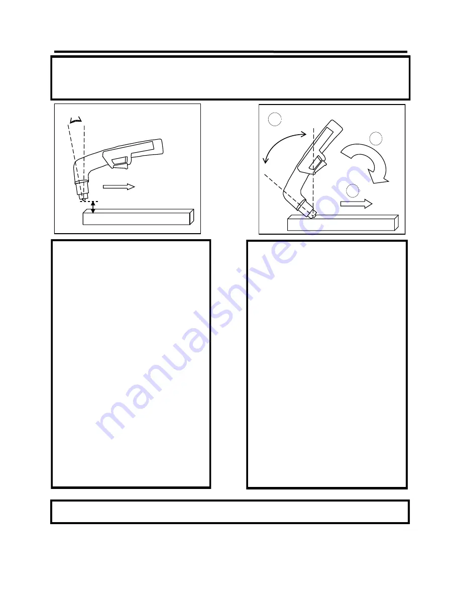
Edge Starts are the best type of start if possible 
to promote consumable and torch life.  This re-
duces blow back of molten material  and allows a 
smooth gradual start of the cut. 
1.  Line up the hole on the  tip of the electrode 

on the edge of the cut. Hold torch perpen-
dicular to the cut initially, about 1/16” off 
the metal. Slide the yellow safety lock and 
squeeze the trigger.  Wait for arc to start. 

2.  Once the arc starts, wait for the arc to pene-

trate all the way through the metal. 

3.  As the torch penetrates its flame all the way 

through the metal, tilt the torch so there is a 
slight lead in the flame if metal is thin. If it is 
thick,  keep holding torch in a nearly vertical 
position. 

4.  Begin moving the torch in the direction of 

the cut.  Maintain 1/16” standoff height. 

5.  Move the torch fast enough so the sparks  

and flame trail from the bottom edge at an 
angle of no more than 30° and no less than 
10° from perpendicular to the metal.  Excess 
angle of sparks/flameindicate too fast of 
travel speed or practical cut capacity has 
been reached.   Little or no angle indicates 
too slow of travel speed. 

IMPORTANT:  If you use a standoff guide with the torch, it must be adjusted or bent to provide no more than 1/8” standoff, less if possible. 
Long standoff heights reduce cut capacity and quality.  It also promotes rapid consumable wear and can prevent the pilot arc from transferring. 

             Basic theory and function 

Section 3 

0°-15° 

TRAVEL 


1/16” 

EDGE START 

40°-60° 

TRAVEL 


PIERCE START 

 Piercing starts often result in rapid consumable 
wear and excess blow back of molten metal de-
posited onto torch and consumables.   This 
should be done only as necessary. 
1.  Tilt  the torch in the direction  of travel or 

toward the side of the metal to be discarded 
or wasted at a 40° to 60° angle. Slide the yel-
low safety lock and squeeze the trigger.  Wait 
for arc to start. 

2.  Once the arc starts, wait for the arc to trans-

fer from pilot arc to the cutting arc. 

3.  As the torch penetrates it flame at an angle 

rotate the torch slowly to the vertical posi-
tion, as the arc penetrates the metal. Tilt the 
torch from 0°-15° for thin metal cuts, or hold 
it nearly perpendicular for thicker metal cuts. 

4.  Begin moving the torch in the direction of the 

cut.  Maintain 1/16” standoff height. 

5.  Move the torch fast enough so the sparks  

and flame trail from the bottom edge at an 
angle of no more than 30° and no less than 
10° from perpendicular to the metal.  Excess 
angle of sparks/flame indicate too fast of 
travel speed or practical cut capaicity has 
been reached.   Little or no angle indicates 
too slow of travel speed. 

The design of the blow back start 

may


cause a slight delay in the arc as the air pressure must built inside the torch 

tubing and head to create the pressure needed to force the electrode off the nozzle seat.  This may take up to two 
seconds.  Restarting the arc with the post flow going may not cause a delay. If the torch does not light after 3 sec-
onds, let go of the trigger and press it again.  If start/arc  is erratic check nozzle and electrode for tightness and wear. 

Содержание PowerPlasma 60S

Страница 1: ...werPlasma 60S 70S and 80S Safety Setup and General Use Guide CC IGBT 1 PHASE Rev 3 0 00215 13 EVERLAST everlastwelders com 1 877 755 9353 Specifications and Accessories subject to change without notic...

Страница 2: ...e at the time of publication this manu al is intended to be a general guide and not intended to be exhaustive in its content regarding safety welding or the operation maintenance of this unit Everlast...

Страница 3: ...nical support available through the main company headquarters available in your country For best service call the appropriate support line and follow up with an email particularly during off hours or...

Страница 4: ...om forums index php Main toll free number 1 877 755 WELD 9353 9am 5pm PST M F 11am 4pm PST Sat FAX 1 650 588 8817 Everlast Canada Everlast consumer satisfaction email sales everlastwelders ca Everlast...

Страница 5: ...t Do not operate the unit until you have read this manual and you are thoroughly familiar with the safe operation of the unit If you feel you need more information please contact Everlast Support The...

Страница 6: ...equip ment If no protection is available exclude them from the work area Even brief expo sure to the rays from the welding arc can damage unprotected eyes Always wear hearing protection because weldi...

Страница 7: ...y burning of the eyes nose or throat are signs that you need to increase ventilation Stop immediately and relocate work if necessary until adequate ventilation is ob tained Stop work completely and se...

Страница 8: ...ion Keep all combustible materials including rags and spare clothing away from area Keep all flammable fuels and liquids stored separately from work area Visually inspect work area when job is complet...

Страница 9: ...tion 1 12 ft S 75 Trafimet Torch Work Clamp NOTE Accessory and consumable style and quantities are subject to change without notice Regulator Assembly with Bracket PowerPlasma 60S 70S and 80S Consumab...

Страница 10: ...uirement 5 CFM 90 psi 30 60 gallon reserve 6 CFM 90 psi 30 60 gallon reserve 7 CFM 90 psi 30 60 gallon reserve Duty Cycle Over Current Protection Yes Yes Yes Minimum Operating Air Pressure Safety Cut...

Страница 11: ...hich rates it for light contact with dripping water It is a good idea to remove the welder from the vicinity of any water or moisture source to reduce the possibility of electrocution or shock Never o...

Страница 12: ...12 QUICK SETUP AND USE GUIDE Section 2 QUICK SETUP GUIDE CONNECTIONS WORK TORCH CENTRAL CONNECTOR...

Страница 13: ...TUBING IMPORTANT TO PREVENT AIR LEAKS MAKE SURE TUBING ENDS ARE SQUARELY CUT AND FULLY INSERTED TO RELEASE TUBING PRESS GENTLY ON PLASTIC COLLAR SO THAT IT COMPRESSES INTO HOUSING AND THEN PULL TUBIN...

Страница 14: ...ND COMMONLY AVAILABLE IS THE REPLACEABLE DESSICANT TYPE USED FOR AUTOMOTIVE PAINTING DAMAGE DONE TO THE TORCH AND THE PLASMA CUTTER INCLUDING BUT NOT LIMITED TO SHORTING CORROSION AND DETERIORATION OF...

Страница 15: ...T 4T LOCK 3 AIR PRESSURE GAUGE 2 AIR PRESSURE OK TO CUT 1 AMP DISPLAY QUICK SETUP AND USE GUIDE Section 2 FRONT PANEL FEATURES AND CONTROLS 10 PILOT ARC OPERATION 4 AMP CONTROL 5 CENTRAL CONNECTOR FUS...

Страница 16: ...propriate to cool the torch and the consumables Post flow time will depend upon the amps and length severity of use A post flow time of 3 5 seconds post flow for every 10 amps is suggested 9 2T 4T Tri...

Страница 17: ...S INLET 1 220 V 1 220 VAC 2 2 POLE POWER SWITCH 5 HF GROUND BOLT 4 GAS INLET 3 POWER CABLE 1 220 240V QUICK SETUP AND USE GUIDE Section 2 REAR PANEL FEATURES AND CONTROLS 1 CNC CONNECTION 6 REGULATOR...

Страница 18: ...Always con sult a licensed electrician who is aware of local codes before attempting any wiring of the welder or of the power circuits Everlast is not responsible for any mis wiring or damage caused...

Страница 19: ...AVEL 1 16 EDGE START 40 60 TRAVEL 1 PIERCE START 2 3 Piercing starts often result in rapid consumable wear and excess blow back of molten metal de posited onto torch and consumables This should be don...

Страница 20: ...h cut Lowering the air pressure below 65 psi to try to get the torch to cut will only result in a lazy wandering arc TIP For longer consumable life do not use the pilot arc unnecessarily Select the 3...

Страница 21: ...SULTS OF CUT AT FAST SPEED SIGNIFICANT SOFT POROUS DROSS RESULTS OF CUT AT SLOW SPEED VERTICAL CUT LINES RESULTS OF TOO MUCH CURRENT OR TOO MUCH STAND OFF HEIGHT SIDE VIEW MELTED TOP EDGE RESULTS OF W...

Страница 22: ...tion of a cut a lead in cut should be employed A lead in is a cut that is made in the disposable part also known as a drop of the object to lead into the main part of the cut so that the destructive f...

Страница 23: ...75 torch nor is it affiliated with Trafimet other than its role as an OEM supplier of torches on PowerPlasma S Series units Not all items accessories and parts depicted are available directly through...

Страница 24: ...e this voltage Pins 4 and 6 provide the divided arc voltage This is selectable by adding a jumper on the CNC circuit board to create either 1 16 th or 1 50th of the raw arc voltage It may be used by s...

Страница 25: ...e Wrong consum ables Poor quality aftermarket consumables Premature wear on consumables Short consuma ble life Uneven wear of consumables melting of cup Moisture oil contamination of consumable Excess...

Страница 26: ...26...

Отзывы: