


5
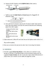
b.
Connect the RJ-45 cable to the
LAN/PoE Cable
of the camera.
RJ-45 Cable
LAN/PoE Cable
c.
Tightly screw the
Cable Gland
and
Screw Cap
to the Rugged RJ-45
Connector Cable.
Screw Cap
Cable Gland
d.
Crimp the RJ-45 connector onto the RJ-45 network cable. Note that the
wires should be placed into the RJ-45 connector based on the following
order (from left to right).
Orange with white stripe
Orange
Green with white stripe
Blue
Blue with white stripe
Green
Brown with white stripe
Brown
5.
Optionally insert a Micro SD card into the card slot (please refer to No.1 in
1.
Physical Description
).
6.
Now you can access the camera live view. See
4. Accessing the Camera
.
3.2
EHN2550-SG
1.
Stick the supplied
Mounting
Sticker
on the surface to mark the 4 screw
positions. Drill the 4 screw-depth holes on the surface and then push the
supplied 4
Screw Anchors
into the screw holes. Optionally drill the bottom 2
Cable Holes if you want to run the cables through the surface.


