background image


33


3.13.3


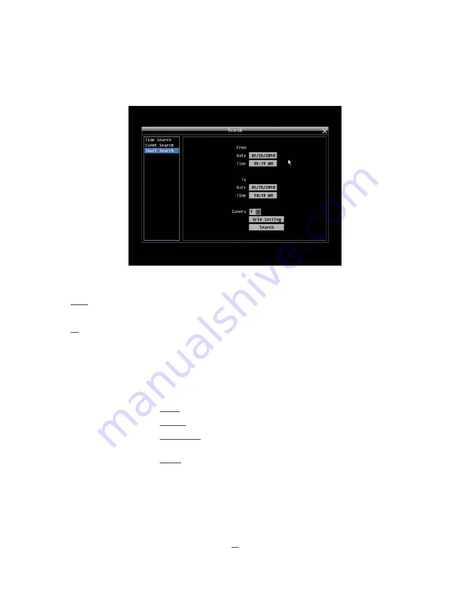
Smart Search 


Figure 3-7 Search Menu – Smart Search 


From   Date


Select start date 

 Time

 Select 

start 

time 

To  

Date


Select end date 

 Time


Select end time 

Camera 

Select which cameras to search for. 

Grid Setting 

Press Grid Setting button to get motion grid setup window. 

Edit Motion Grid 

Press this button to edit the motion grid (See  


Figure  4-5  Camera 

Menu – Motion Grid 

Setting

).  

Set All: Press this button to select the entire area. 
Clear All: Press this button to clear all the grids selected. 
Save & Back: Press this button to save the motion grid setting and return to 
motion setting menu. 
Cancel: Press this button to cancel all changes and returns to the motion 
setting menu. 

Содержание ECOR 264x1-16

Страница 1: ...anual E EC CO OR R 2 26 64 4x x1 1 D Di ig gi it ta al lr re ek ko or rd de er r E EC CO OR R 2 26 64 4x x1 1 1 16 6 E EC CO OR R 2 26 64 4x x1 1 9 9 E EC CO OR R 2 26 64 4x x1 1 4 4 2010 EverFocus Electronics Corp ...

Страница 2: ... the appliance when it is dirty When the dirt is hard to remove use a mild detergent and wipe gently Do not overload outlets and extension cords as this may result in a risk of fire or electric shock Do not operate the appliance beyond its specified temperature humidity or power source ratings Do not use the appliance in an extreme environment where high temperature or high humidity exists Use the...

Страница 3: ...ges or modifications not expressly approved by the party responsible for compliance could void the users authority to operate this equipment WEEE The information in this manual was current upon publication The manufacturer reserves the right to revise and improve his products Therefore all specifications are subject to change without prior notice Manufacturer is not responsible for misprints or ty...

Страница 4: ...9 5 Speed Dome Installation 11 1 10 USB MOUSE INSTALLATION 12 1 11 NETWORK CONNECTION 13 1 11 1 Direct PC Connection through Crossover Network Cable 13 1 11 2 Network Connection through Patch Cable 14 1 12 FINAL INSTALL PROCESS 14 2 MOUSE AND FRONT PANEL OPERATION 15 2 1 GENERAL USB MOUSE OPERATION 15 2 1 1 How to select a channel Enable audio 15 2 1 2 OSD Root Menu 15 2 1 3 Operation in the Confi...

Страница 5: ... 13 4 Snapshot Search 35 3 14 COPY 36 3 15 LOGOUT 36 4 DVR CONFIGURATION 37 4 1 CONFIGURATION MENU 37 4 2 EXPRESS 37 4 3 CAMERA SETTING 40 4 3 1 Basic Setting 40 4 3 2 Video Adjust 42 4 3 3 Motion 43 4 3 4 Video Loss 46 4 4 RECORD PLAY SETTING 47 4 4 1 Record 47 4 4 2 Built in Calculator 48 4 4 3 Play 49 4 5 ALARM EVENT SETTING 50 4 5 1 Alarm 50 4 5 2 Event 52 4 6 SCHEDULE SETTING 61 4 6 1 Express...

Страница 6: ...ESS 91 5 4 VIRTUAL PORTS 92 5 5 PRE INSTALLATION 92 5 6 WHAT IS YOUR NETWORK SETUP 93 5 7 SIMPLE ONE TO ONE CONNECTION 94 5 8 DIRECT HIGH SPEED MODEM CONNECTION 98 5 9 ROUTER OR LAN CONNECTION 100 6 REMOTE OPERATION FROM BROWSER 103 4 11 3 Installing ActiveX controls 104 4 11 4 Enabling ActiveX Controls 107 6 2 REMOTE LIVE VIEW 110 6 3 REMOTE PLAYBACK 110 7 EVERFOCUS DDNS SETUP 112 8 TROUBLESHOOTI...

Страница 7: ...be operated via the front panel buttons or mouse The ECOR264 4 ECOR264 9 ECOR264 16 DVR is engineered for express operations Setup copy search and playback recordings in seconds with a simple point and click on the command icons 1 1 FEATURES H 264 Compression format Pentaplex Operation Simultaneous live recording playback archiving and remote viewing User friendly GUI with graphical icons and visu...

Страница 8: ...hedule and Event Playback Search By Date Time and Event Alarm In 16 9 4 Alarm Out 4 relay output 1 relay output Video Pause Yes Video Loss Detection Yes Motion Detection Yes Event Log Yes Watch Dog Timer Yes Internal HDD 1 hot swappable or 2 internal HDD Built in DVD Burner Slim Type DVD Burner Optional User Interface GUI Graphical User Interface OS Embedded Linux Network Protocol Gigabit Ethernet...

Страница 9: ...ding on playback mode 6 I I Reverse playback or pause 7 Stop playback 8 I I Forward playback or pause 9 I Fast forward playback or step forward playback depending on playback mode 10 View Press this key to switch between 4x PiP Picture In Picture full screen 9x 10x 13x and 16x Note PIP display is not available in playback mode 11 SEQ Press this key to enter the auto sequential switching mode on se...

Страница 10: ... zoom off 15 SEARCH Press this key to enter Search Menu For more detail about the Search function please see Section 3 13 Search 16 Menu ESC Press this key to enter exit MAIN SETUP MENU 17 Copy Press this key to enter Copy Menu video data export For more detail about Copy function please see Section 3 14 Copy 18 ENTER ARROW keys Instead of or in combination with a mouse you can use these keys to c...

Страница 11: ...e of traffic 6 USB 1 0 USB port for USB mouse 7 RS232 socket 9 pin D Sub control input for RS 232 for service purpose 8 RS485 socket Interface for remote control via RS 485 keyboards and telemetry control of connected PTZ devices 9 MAIN Composite BNC output for main monitor Live Playback Setup 10 Call Composite BNC output for CALL monitor Live only incl multi view 11 Main VGA Main monitor connect ...

Страница 12: ...RG 58 antenna cable and other types of coaxial cable are not compatible All connected video sources must provide a 1 Vpp NTSC or PAL standard video signal When converting transmission lines twisted pair fiber optics radio to the video inputs be sure to verify accurate receiver calibration and signal levels ATTENTION In order for the system to auto detect the appropriate video format NTSC or PAL ma...

Страница 13: ...oax cable and RCA plugs AUDIO RECORDING FUNCTIONALITY The audio channels 1 4 are assigned to the video input channels 1 4 for recording playback and network stream Audio recording is activated deactivated in the Camera Menu for Camera 1 4 Please check and always comply with local laws and regulations when using audio recording The audio channels are always recorded together with video and is indep...

Страница 14: ...is DVR provides one alarm input per camera All inputs are programmable N O Normal Open or N C Normal Closed inputs have to be switched by dry contacts Alarm input with N O Normal Open contact Alarm input with N C Normal Closed contact in idle state contacts 9 16 similar in idle state contacts 9 16 similar All settings are programmed in the ALARM menu Section 4 5 1 1 8 2 Alarm Output Relay The rela...

Страница 15: ...are expected to be highly susceptible to interference The number of devices installed in one bus is limited to 32 and the maximum cable length is 3 900 feet Both of these can be expanded using a signal distributor see below Both the first and the last device in series should be terminated with 120 Ohm resistance in order to minimize line reflections RS 485 bus serial wiring Cable length from box t...

Страница 16: ...re e g the interconnection of several keyboards is not possible with these types of signal distributor 1 9 2 RS 485 socket pin assignment The RS485 pin assignment is as follows 1 9 3 EKB 500 connection with network patch cable For a simple short distance installation recorder and keyboard can be connected directly using a standard CAT5 network cable with an 8 pin connector at only one end and at t...

Страница 17: ...y the optional EKB 500 keyboard Supported protocols EverFocus Pelco D Pelco P Samsung Transparent Required DVR settings RS 485 receiver address in CAMERA menu Section 4 3 RS 485 parameters and protocol in the I O CONTROL menu Section 4 10 4 ATTENTION Some Pelco D P protocol domes and receivers require an address offset of 1 i e the address assigned to the dome receiver in the DVR camera menu must ...

Страница 18: ...back panel USB port possible also in operation The rear USB V1 0 port is recommended to reserve the higher speed front USB V2 0 port for video copy export NOTE Recommended mouse types are Logitech and Microsoft wired USB wheel mouse Wireless USB mouse is not supported ...

Страница 19: ... types of connection 1 11 1 Direct PC Connection through Crossover Network Cable The point to point connection of DVR and PC requires a crossover crossed network cable This type of connection is ONLY used for direct connection to a single PC Make sure that the PC is equipped with a 10 100 1000 Mbps compatible network connection Figure 1 3 Direct PC Connection Pinout of crossover cable ...

Страница 20: ...ork switch or router Figure 1 4 Network Connection through Patch Cable Pinout of straight patch cable 1 12Final Install Process Once you have completed the basic wiring connections you are ready to turn on the DVR Simply plug in the power source The POWER LED will light up if power is normal Once the system has finished loading you can begin to set up the menu options for the DVR ...

Страница 21: ...een will be highlighted by a white frame 2 Double clicking on a channel screen will display full screen for this channel 3 To enable audio out click the audio icon ex at lower side of the screen This system has only one audio out Click this button to enable or disable the audio out mode 2 1 2 OSD Root Menu 1 Right click the mouse to obtain the DVR control bar see Figure 2 1 OSD Root Menu When you ...

Страница 22: ...ck on a choice to select it 3 In section 3 all the options for the selected choice will be available Click on a field to make changes 2 1 4 Field Input Options The following are examples of different types of fields available in the Configuration menu Textbox Click on the box and an on screen keyboard will appear see note about the on screen keyboard below Dropdown box Click on the down arrow to s...

Страница 23: ...or Right Note about on screen keyboard Click on a button to input that character The buttons on the right and bottom have the following functions Space Enter a space Caps Switch to capital letters Delete the letter Confirm the selection Move to right Move to left ...

Страница 24: ...isplayed on top of the control bar 2 Press Enter key on any icon to perform that action These actions are covered in detail in Chapter 3 3 Press Menu to close the DVR control bar 2 2 3 Front Panel Key Review The basic principle of front panel operation is to use arrow keys to navigate among the menu items Use the Enter key to confirm a selection or enter the next level menu Press the Menu key to e...

Страница 25: ... to move between items and press Enter to make changes Note press Menu button to go back to the previous menu section 2 2 5 Field Input Options Textbox Press Enter key and an on screen keyboard will appear see note about on screen keyboard below Dropdown box Press Enter key to show the available options Use arrow keys to highlight the desired option and press Enter again to select it Check box Pre...

Страница 26: ...oard Click on a button to input that character The buttons on the right and bottom have the following functions Space Enter a space Caps Switch to capital letters Delete the letter Confirm the selection Move to right Move to left ...

Страница 27: ...R will follow the record settings of the schedule 3 2 Login In order to access ECOR264x1 options users may be asked to log in for authority identification depending on settings for USER LOGIN menu SYSTEM USER chapter 4 10 3 To log in follow these steps 1 Right click on the screen or press the Menu Key to display the Main Menu 2 Choose or click or press Enter key on the Configuration icon to bring ...

Страница 28: ...Enter key on the front panel to confirm the password Click or press Enter key on the Login button to log in to the system Figure 3 2 On screen Keyboard 3 3 Select Camera operation ECOR264x1 is a pentaplex DVR users can control each camera individually by selecting that camera For camera selection Mouse Right click the screen the image will show a white frame on screen if the camera has been select...

Страница 29: ...on is as follows To playback By mouse Right click to bring up the menu bar and click on to enter Playback Menu By front panel Press key to enter Playback Menu The playback bar will show see figure below 2009 05 25 09 09 30PM 2009 05 25 09 09 40PM 2009 05 25 09 10 30PM 1 Stop key press to stop playback 2 Slow Reverse key press to start slow reverse playback 3 Pause key press to pause playback 4 Slo...

Страница 30: ...r is 30 hours L3 Entire time bar is 1 hour L4 Entire time bar is 10 minutes L5 Entire time bar is 1 minute 11 Express copy Press to start express copy when camera during playback only one camera 12 Playback speed indicator 13 Press X to close the playback bar 14 Start time for bar the left most point of the time bar 15 Current playback time the time indicated by the slider 16 End time for time bar...

Страница 31: ...t Position PRESET number DELETE Start Preset Tour TOUR number GO Start Pattern PATTERN Note The PATTERN commands vary depending on dome model manufacturer Please consult documentation of the speed dome for details Start Auto Pan AUTO PAN Open Setup Menu PRESET 95 SET Enter in Speed Dome OSD I iris open ESC Cancel in Speed Dome OSD I Iris close Pan Tilt direction keys Zoom in Zoom out Focus far Foc...

Страница 32: ... With Quick Mouse Control the user can control PTZ direction zoom and focus by clicking directly on screen The screen is divided into 16 areas with the outer ring is divided into 12 zones used to control movement direction The inner square of 4 areas is used to control zoom and focus Figure 3 3 Express Control PTZ The screen is divided into a 4x4 grid The function of each section is defined as bel...

Страница 33: ...scroll through each display format 3 7 1 Bring to full screen mode By mouse Double left click on the selected channel to put that camera in full screen mode By front panel Press any channel key to bring that channel to full screen mode 3 8 CHANNEL SWITCHING Use this function to change channel position 1 Select one camera 2 Press Channel button 3 Click on the channel number you wish to select on th...

Страница 34: ...ress again to show status information Please see the following table for status representation Alarm Audio Event HDD failure HD temp too high Seq Motion Video loss No network 4 Press again to show both status information and camera information 5 Press again to hide all information 3 10 SEQUENCE 1 By mouse Click Sequence button to enter the auto sequential switching mode 2 By front panel Press the ...

Страница 35: ...ol from front panel Click Monitor button on front panel to toggle monitor control between MAIN and CALL monitor Note Holding MONITOR key 1 second will switch Main monitor display between VGA and BNC output The deactivated video output will show a message The monitor is currently unavailable Please hold Monitor key to switch Operation of Call Monitor OSD If the CALL monitor is selected the OSD main...

Страница 36: ...on in different areas of the screen Users can control the portion of the magnified image to be displayed by clicking directly on screen Figure 3 4 Zoom Express Control The screen is divided into a 4x4 grid The function of each section is defined as below 1 Left and up 2 3 Up 4 Right and up 5 9 Left 8 12 Right 13 Left and down 14 15 Down 16 Right and down 6 7 10 11 Not used 1 2 3 4 5 6 7 8 9 10 11 ...

Страница 37: ... Search Figure 3 5 Search Menu Time Search Play From Select the time to begin the search by choosing the Date and Time Click on the Play button to start the search The DVR will automatically play the video being searched The DVR will play the nearest time if there is no data in selected time In search playback mode press the Stop button to return to the search menu ...

Страница 38: ...ect which cameras to search for Event Select which event type s to search for Choose from Alarm Motion Video Loss or Others Click on the Search button to start searching The search results will be shown as a list of events Prev Page Go to previous page Next Page Go to next page Play Playback selected item Copy Copy selected item ...

Страница 39: ...ton to get motion grid setup window Edit Motion Grid Press this button to edit the motion grid See Figure 4 5 Camera Menu Motion Grid Setting Set All Press this button to select the entire area Clear All Press this button to clear all the grids selected Save Back Press this button to save the motion grid setting and return to motion setting menu Cancel Press this button to cancel all changes and r...

Страница 40: ...motion grid 2 Use arrow keys to select one corner of desired area 3 Press Enter key at the starting point 4 Use arrow keys to select motion area Press Enter key twice at the end point and the area will be selected Search Click on the Search button to start searching The search results will be shown as a list of events Prev Page Go to previous page Next Page Go to next page Play Playback selected i...

Страница 41: ...e Enter start date and time of the search Search direction Backward The search will be proceeded before entered start date time Forward The search will be proceeded after entered start date time Search camera Select a camera for the Snapshot search Result interval Enter the interval time between the thumbnail images range 1 min 1 day Operation icons in Snaphot search result Next snapshot page Exit...

Страница 42: ...elect the start date time to be archived End Date Time Select the end date time to be archived Copy To Select whether you want to copy to USB or CD DVD DVR models with DVD option only Data Size Shows the estimated total file size for the time period Copy Now Press Copy button to start archiving 3 15 LOGOUT Right click to bring up the menu bar and click the button to bring up the Logout Confirmatio...

Страница 43: ...ter the Configuration Menu 4 2 EXPRESS The Figure 4 1 Express Menu is a screenshot of the EXPRESS SETTING MENU This menu is used to configure global express settings for all cameras For example if user selects Event Only in Record Mode and presses the Apply button all 4 8 cameras will be set to Event only If user selects Blank in Recording Mode and presses the Apply button cameras will keep their ...

Страница 44: ...t Quality Standard and Extended Record in the next column For more detail please refer to APPENDIX B RECORDING VALUE SELECTION RULES Recording Days Set the maximum recording days Available selection will be shown in the next column including 1 3 5 7 14 20 30 40 50 and 60 days DVR will auto adjust relative settings for all the cameras to fit the selected max recording days For more detail please re...

Страница 45: ...ur network When DHCP is selected and an internet connection is available this value will be assigned automatically This field must be assigned correctly if you plan to use the DDNS feature see Section DDNS for more details DNS server 2 This field shows the secondary DNS server for your network Apply Press Apply button to save and apply the Express settings to DVR The system will automatically adju...

Страница 46: ...ties any unused cameras should have this option set to disabled Covert Check the box to hide the camera picture in live and sequence modes However the image will still be recorded and can be played back by any user who has playback rights Record Mode 2 record modes are available Normal Event This recording mode includes continuous and event recording Event Only Video will be recorded only when eve...

Страница 47: ... the settings for all cameras will return to previous values Event Speed Maximum desired frame rate in images per second IPS for event recording if more than one camera requires simultaneous event recording the total for all cameras cannot exceed the maximum available FPS for the DVR at that resolution setting and the available FPS may be divided across the cameras Record Audio Camera 1 4 screen o...

Страница 48: ...rs too saturated or if the colors appear overwhelmed by glare try decreasing the Brightness Contrast Adjusts the contrast in the selected video channel If details are lost or lines appear distorted try decreasing the contrast Color Adjusts the color tone in the picture Apply To This button can be used to copy the video settings to other cameras Select which cameras you wish to copy to Select All s...

Страница 49: ... the event camera will display on the call monitor Pre alarm Record Check box to start copying recorded video to the hard disk from several moments before the motion event Pre alarm recording rate will follow Normal frame rate setting Buzzer Check this box to enable the buzzer when a motion event is triggered Email Notify Check this box to send email notification when a motion event is detected Em...

Страница 50: ...om 1 lowest to 10 highest Min Area To avoid false detections by small objects this value defines how many grids have to be exceed threshold before generating a motion event Select a value between 1 default to 5 grids Preview Preview the motion grid Set All Press this button to select the entire area Clear All Press this button to clear all the grids selected Save Back Press this button to save the...

Страница 51: ...Apply To This button can be used to copy the motion settings to other cameras Select which cameras you wish to copy to Select All selects all cameras Unselect All deselects all cameras Click OK to copy the settings or Cancel to exit without copying ...

Страница 52: ...occurs Email operation requires that valid email settings have been entered in the Network Setting Email setup screen Network Alarm Check box to send out a network alarm to client PC when video loss occurs requires PowerCon software and proper settings for the Alarm Server in the Network Setup menu Alarm Output Selection of relay output as event reaction NONE not active 1 4 for the relais in 4 cha...

Страница 53: ... Menu 4 4 1 Record Record Overwrite Check the box and disk will begin overwriting when full NOTE Unless this box is checked the DVR MUST STOP RECORDING WHEN THE DISK IS FULL The use of record overwrite is strongly recommended If you do not use this feature please be sure to make specific arrangements to monitor be notified when the disk is full Schedule Record Activate this check box for using sch...

Страница 54: ...he maximum hard drive space choose OFF See Record Overwrite and notes above 4 4 2 Built in Calculator The built in record period calculator can give a rough estimation of the total recording time for the DVR with current settings In order to compute as accurate an estimate as possible please enter your estimates for the hours per day you expect recording to take place due to motion events and due ...

Страница 55: ...tion as described below Playback From X Seconds ago When the DVR is put into playback press PLAY it will begin playing from the selected time Choose from 60 to 3600 seconds prior to the present time If Quick Playback is not enabled pressing the PLAY button will start playback from last viewed playback position ...

Страница 56: ... frame rate setting Buzzer Check this box to enable the buzzer when an alarm occurs Main Monitor Main monitor display options when a motion occurs No change No change on the main monitor display Full screen A full screen of the active camera will display on main monitor Call Monitor Call monitor display options when a motion occurs No change No change on the main monitor display Full screen A full...

Страница 57: ...hoosing the desired PTZ preset number Auto Lock Check the box and the events will be recorded in the write protected segment of the Hard Disk DVR will lock a period of time when alarm happen the length of time will depend on DVR setting Alarm Output Selection of relay output as event reaction NONE not active 1 4 for the relay in 4 channel version is only 1 relay available Output Type Output action...

Страница 58: ...HD Full If the DVR is not set to Overwrite in the Record Menu an event will be created when the HDD is filled HD Off If HDD are switched off or are removed the DVR will create an HD OFF event Power Loss If power is disconnected Record Stop If DVR stops recording process Network Loss If connection to the local network is lost DVR will create a Network Loss event NOTE This function only checks the p...

Страница 59: ...d email settings have been entered in the Network Setting Email setup screen Network Alarm Check box to send out a network alarm to client PC requires PowerCon software and setting up Alarm Server in Network Setup menu Alarm Output Selection of relay output as event reaction NONE not active 1 4 for the relay in 4 channel version is only 1 relay available Output Type Output action will be Transpare...

Страница 60: ...creen Network Alarm Check box to send out a network alarm to client PC requires PowerCon software and setting up Alarm Server in Network Setup menu Stop Recording Check box to stop recording when HD s temperature is over the Temp Warning Limit Temp Warning Limit Sets the trigger temperature for HD Temperature event actions Choose between 55 C 131 F or 85 C 185 F Alarm Output Selection of relay out...

Страница 61: ...t valid email settings have been entered in the Network Setting Email setup screen Network Alarm Check box to send out a network alarm to client PC requires PowerCon software and setting up Alarm Server in Network Setup menu Alarm Output Selection of relay output as event reaction NONE not active 1 4 for the relay in 4 channel version is only 1 relay available Output Type Output action will be Tra...

Страница 62: ...n Network Alarm Check box to send out a network alarm to client PC requires PowerCon software and setting up Alarm Server in Network Setup menu Alarm Output Selection of relay output as event reaction NONE not active 1 4 for the relay in 4 channel version is only 1 relay available Output Type Output action when alarm is triggered Timeout Alarm output lasts for the set time duration Permanent Alarm...

Страница 63: ...erCon software and setting up Alarm Server in Network Setup menu Alarm Output Selection of relay output as event reaction NONE not active 1 4 for the relay in 4 channel version is only 1 relay available Output Type Output action when alarm is triggered Timeout Alarm output lasts for the set time duration Permanent Alarm will be continuously active until user presses Enter key Transparent Alarm out...

Страница 64: ...ail Notify Check box to enable email notification when power has been restored Email operation requires that valid email settings have been entered in the Network Setting Email setup screen Network Alarm Check box to send out a network alarm to client PC when power has been restored requires PowerCon software and setting up Alarm Server in Network Setup menu ...

Страница 65: ...tive 1 4 for the relay in 4 channel version is only 1 relay available Note In this operation mode the relay is powered if record stops If record is stopped due to power loss there will be no reaction If relay reaction is needed also in case of power loss please use the RECORD STATUS RELAY OUTPUT in RECORD menu chapter 4 4 1 RECORD Output Type Output action when alarm is triggered Timeout Alarm out...

Страница 66: ...lasts for the set time duration Permanent Alarm will be continuously active until user presses Enter key Transparent Alarm output remains active until event ends Trans Timeout Alarm output continues until event ends then lasts for the set time duration Timeout Duration The amount of time the buzzer sounds when DVR stops recording Duration selectable from 1 to 150 seconds NOTE This function only ch...

Страница 67: ...ds when Daytime begins Daytime End Select weekday daytime ending time Nighttime schedule begins when Daytime ends Record Type Select the type of recording for each time period Disabled No recording during scheduled time period Normal Event Continuous and Event recording Event Only Event recording only Normal Frame Rate Continuous FPS recording rate for the scheduled time period The maximum rate is...

Страница 68: ...4 21 Schedule Menu Holidays Date Type Select one of the 2 day types HOLIDAY or OTHERS Recurrent Type Select one of the options for entering the date One time Input of a single date not repeated in following years Month Date Input of month and date this Holiday will be repeated in following years Month Weekday Input of month and day of the week this Holiday will be repeated in following years Detai...

Страница 69: ...istinguish each recoding mode Gray No Rec No recording during this time block Orange E Only events are recorded during this time block Blue N E Default Normal and event recording during this time block To Set Schedule using Mouse 1 Click on desired start time block no numbers on it on a time bar At this time the selected block will be highlighted in blue frame and the selected time bar will be hig...

Страница 70: ...dule setting mode press Enter button to enter schedule setting mode At this time the whole editing area at right down side will be highlighted within a blue frame See below image 2 Enter camera selection mode Use Up Down arrow key to switch to Camera selection mode When Camera selection mode is selected all cameras will be highlighted in a blue frame See below image 3 Selecting camera Use Right Le...

Страница 71: ...llowing blocks will turn into gray which means this gray timezone has been set to the recording mode of gray No Rec User can also change the timezone to a different record mode with different color by following instruction in next step 7 Changing recording mode color of a timezone Use Right Left arrow key to switch to the first block with number on it of a timezone Clicking Enter button and this t...

Страница 72: ...cording rate of the DVR divided by the number of installed cameras Event Frame rate in images per second for event recording Event record speed can be set from 1 to 30 25 for PAL The sum of the normal and event record fps during event recording cannot exceed the maximum record rate of the DVR Action Check this box to enable notifications enabled elsewhere Buzzer Alarm out E mail and Network when a...

Страница 73: ...ameras you wish to copy to Select All selects all cameras Clear All deselects all cameras Click OK to copy the settings or Cancel to exit without copying ATTENTION All defined settings in this menu are only active if the check box SCHEDULE RECORD in RECORD menu chapter 4 41 RECORD is activated ...

Страница 74: ...d by red frame There are 24 blocks on the time bar representing 24 hours respectively Set a schedule start time by clicking on a desired start time block on a time bar and clicking again to confirm it At this time the selected block and all following blocks will turn gray which means this gray timezone has been set to the recording mode of gray alarm action recording off 2 Click again to confirm t...

Страница 75: ...mage 4 Enter time bar editing mode Use Up Down arrow key to switch to time bar editing mode When this mode is selected all 9 time bars will be highlighted within a blue frame 5 Select desired time bar for setting press Enter button the first time bar will be selected for setting and highlighted in a red frame See below image Use Up Down arrow key to desired time bar for setting 6 Editing blocks in...

Страница 76: ...g to another recording mode The color switch sequence is gray orange Apply to Days This button can be used to copy schedules to other days Select which days you wish to copy to Select All selects all days Clear All deselects all days Click OK to copy the settings or Cancel to exit without copying Apply to Cameras This button can be used to copy schedules to other cameras Select which cameras you w...

Страница 77: ...ly Subnet Mask This field shows the subnet mask for your network so the DVR will be recognized within the network If DHCP or PPPoE is selected this value will be assigned automatically Gateway This field shows the gateway for your network so the DVR will be recognized within the network If DHCP or PPPoE is selected this value will be assigned automatically DNS Server 1 This field shows the primary...

Страница 78: ...ary for the DVR to communicate with the DDNS server You can obtain the actual DNS IP from your Internet Service Provider ISP or from a PC located on the same LAN as the DVR go to http www dnsserverlist org to obtain a list of the IP addresses of their recommendation of the best servers to use for your location 2 If you are connecting through a router make sure that you have opened up all the requi...

Страница 79: ...am access by mobile phone Please consult Appendix D Mobile Phone Viewing for details 4 7 2 EMAIL Figure 4 26 Network Menu Email SMTP Server Assign the SMTP e mail server s name Note For more reliable email service use the server s IP address SMTP Port Assign the port number used by the SMTP server Authentification Activate the check box if the SMTP server requires an authentication user name passw...

Страница 80: ...racters particularly _ In the DVR s Network Menu above go to DDNS Choose everfocusddns com for the Server and put in your chosen name verified available and without special characters for DVR Name hostname Press the Select or Submit Update button to synchronize the DVR with the DDNS server You should see an indication of Success on the screen If you see Could Not Find Server or any other error mes...

Страница 81: ... dyndns org Host name Host name created through the dyndns account User name User name of the dyndns account Password Password of the dyndns account Confirm Re enter password Note For more details on DDNS setup please see Chapter 7 Everfocus DDNS Setup ...

Страница 82: ...ver IP 1 3 Enter the IP addresses of the receiving alarm servers Protocol Type Select the protocol type UDP User Datagram Protocol TCP Transmission Control Protocol Note Use UDP only for LAN applications this mode is not safe for Internet connections Port Transmission port for network alarm messages Network ID Enter the network ID Unique ID for network alarm Note 1 The ID must contain 10 numbers 2...

Страница 83: ...Start Shows earliest recorded time on the hard drive Record Time End Shows latest or most current recorded time on the hard drive Disk Select disk number Health Status Displays current status of the selected disk Disk Temperature Displays current disk temperature Disk Size Total Shows total disk size Disk Size Usage Shows percentage of used disk space If DVR is set to automatically overwrite the d...

Страница 84: ...k percentage protected records can be enabled disabled by different methods 1 Camera Basic Setting Motion Auto Lock 2 Alarm Event Alarm Auto Lock 3 Lock or unlock the file manually in search result list Current Lock Current lock percentage of HDD volume If locked data has reached the maximum lock percentage it will stop lock new data Unlock All Click this button to unlock the locked part of HDD De...

Страница 85: ...ay camera titles Date Time Check the box to display current date time Playback Date Time Check the box to display playback date time Playback Status Check the box to display playback status Event Status Check the box to display event status HDD Status Check the box to display hard drive status Text Insert Reserved function display data transmitted from external RS232 device Monitor Output Select F...

Страница 86: ...an be set from 0 to 99 seconds Sequence repeats continuously from steps 1 through 20 until interrupted 4 9 3 Call M T SEQ Figure 4 34 Display Menu Main M T SEQ Step Sequence order For reference Camera Select which camera appears in the current step Dwell sec Set the dwell time for each step Sequence dwell time can be set from 0 to 99 seconds Sequence repeats continuously from steps 1 through 20 un...

Страница 87: ...t time format 12H or 24H Time Zone Select the time zone of current location NTP Enable disable automatic time synchronisation by NTP server NTP Server Enter IP Address of a valid NTP server To find a compatible NTP address please follow these steps a Go to a PC that is connected to the internet b Click on START RUN type command and press OK c In the DOS Prompt type ping pool ntp org to find out th...

Страница 88: ...g Start Date Start date of Daylight Saving period Start Time hh mm Enter time when daylight saving period begins Set To hh mm Enter the new time for begin of Daylight Saving period For most regions this will be one hour ahead of the Start Time End Date End date of daylight saving time End Time hh mm Enter the time when daylight saving time ends ...

Страница 89: ...set access levels See the chart on next Page for a listing of the rights associated with each access level Figure 4 37 System Menu User The default settings provide 3 users with different user rights User Name Password User Right Level admin 11111111 Admin user1 22222222 Manager user2 33333333 Operator ...

Страница 90: ...dit button to make changes to an existing user account Press Save button to save changes or Cancel to exit without making changes Figure 4 39 System Menu User Edit User Login Check this box to activate user login When this is disabled no username or password is required to access the system and all users operate with ADMIN rights Auto Logoff Check this box to automatically logoff the current user ...

Страница 91: ...tor Network Operation Live Views PTZ View covert cameras Playback Search Copy Export Info Menu View Log Delete Log Setup Menu Edit own user name password Local Operation Live Views Display OSD ON OFF OSD Settings Sequence PTZ View covert cameras Playback Search Info Menu View Log Delete Log Setup Menu Edit own user name password ...

Страница 92: ...7 bit Stop Bit This field is to set the stop bit for the RS232 connection There are two different stop bits 1 or 2 bit Parity This field is to select the parity level at which you will be connected You can choose between None Odd or Even parity levels RS485 PTZ Protocol PTZ protocol for connected PTZ camera select protocol type EverFocus Pelco D Pelco P Samsung Electron or Transparent In Transpare...

Страница 93: ...ber on the remote control 4 10 5 Misc Figure 4 41 System Menu Firmware Misc Firmware Current Firmware Version Displays the current version Firmware Upgrade Press Upgrade to upgrade the firmware NOTE To perform a Firmware Upgrade you will need to connect a USB flash device with the latest version of the firmware Do not disconnect the USB device or turn off the power to the unit during the upgrade t...

Страница 94: ...rmation 4 42 is a screenshot of the INFORMATION MENU This menu displays important system information Figure 4 42 Information Menu System 4 11 1 System System Version Displays firmware version number Model Displays DVR model number NTSC PAL Displays current video format Network IP Displays the DVR s current IP Address MAC Unique address of the DVR s internal network card This option cannot be chang...

Страница 95: ...played Time Select start time of log to be displayed To Date Select end date of log to be displayed Time Select end time of log to be displayed Log Type Configurations Configuration changes Event Recording and system events Record Recording activities Operation Other operations User User logins logouts View Log Press View Log button to view the log See Figure 4 44 for more detail Clear Log Press C...

Страница 96: ...90 Export Log to USB Press Export button to export log data to USB Figure 4 44 Log List Prev Page Go to the previous page of log Next Page Go to the next page of log Close Close the window ...

Страница 97: ...hree octets of an IP address is often the same for all computers in the local area network For example if a total of 253 computers exist in a single LAN the IP addresses could be assigned starting with 192 168 1 x where x represents a number in the range of 2 to 254 In IPP address could be compared with a telephone number 5 2 Subnet Masks Each host in a LAN has a subnet mask The subnet mask is a s...

Страница 98: ...ion point for peripheral devices such as serial parallel and USB ports Another analogy would be if a WAN IP address is similar to the phone number identify a site IP ports are similar to telephone extensions in that they allow communication with specific devices within a site that all share the same external WAN IP address A router is a device which allows multiple computers and other IP enabled e...

Страница 99: ...t by name See Chapter 7 for details on using EverFocus DDNS What type of DVR are you installing ______________ The default ports are ECOR264 80 Paragon 80 ECOR 80 1600 EDR EDVR 80 1600 and 37260 37263 If the ports were changed in the Network Setup use those port numbers 5 6 What is your Network Setup Everfocus DVR s can operate using one of three types of networking connections 1 Simple One to One...

Страница 100: ...ication Once you have a cross over cable plug one end into the LAN port on the back of the DVR and the other into the network card on the back of the computer Log into the EverFocus DVR menu and go to the Network Setting Menu You must use the Static IP option for this type of connection Assign an IP of 192 168 001 003 a Subnet Mask of 255 255 255 000 and a Gateway of 192 168 001 001 You can ignore...

Страница 101: ...95 To assign a fixed IP address in Windows 2000 XP ...

Страница 102: ...96 ...

Страница 103: ...ssign an IP address of 192 168 1 2 a Subnet Mask of 255 255 255 0 and a Default Gateway of 192 168 1 1 then click OK Restart both the computer and the DVR To access the DVR from the computer simply open Internet Explorer and in the address bar type http 192 168 1 3 ...

Страница 104: ...sing one if you have never made a straight through cable Please remember you can not use a cross over network cable for this application Once you have a straight through cable plug one end into the LAN port on the back of the recorder and the other into the high speed modem Log into the EverFocus DVR menu and go to the Network Setting Menu Input the Static IP address the Subnet Mask and the Gatewa...

Страница 105: ...it from the DVR s Menu to save the settings To access the DVR from a computer open Internet Explorer and in the address bar type http IP address given by your internet service provider Note When using this type of connection only one device can be connected to the modem at a time You will need to use a computer at a different location to test the connection ...

Страница 106: ...hase or make a straight through cable We recommend purchasing one if you have never made a straight through cable Please remember you can not use a cross over network cable for this application Once you have a straight through cable plug one end into the LAN port on the back of the recorder and the other into the router Log into the EverFocus DVR menu and go to the Network Setting Menu ...

Страница 107: ...tion will be displayed on a screen similar to the one below o In Windows Vista look for the information that says IP v4 Take the values for Subnet Mask and Default Gateway and input them into the DVR these values should be exactly the same in both devices However you should change the last number of the IP address For example if the IP address of the computer is 192 168 2 101 the DVR s IP address ...

Страница 108: ...nk router see Chapter 9 for basic support on setting up ports For any other router you will need to contact the manufacturer for support To access the DVR from a computer simply open Internet Explorer and in the address bar type http the IP address given by your internet service provider Note If you changed to a different port other than 80 you will need to include this at the end of the IP addres...

Страница 109: ...onnection http IP address given by your Internet Service Provider IP port used The login page will appear on the screen similar to the one shown above Enter a user name and password to access the recorder These can be changed in the System section of the Main Menu The default user name is admin The default password is 11111111 Click on the Login button and you will log in to the recorder s Network...

Страница 110: ... a screen like the one below If you do not see a yellow bar like the one the arrow is pointing at your security settings may be too high If so go to Section 6 2 2 Enabling ActiveX Controls Right click on the yellow bar and select Install This Add on Install the ePlusDVR cab file when prompted to do so ...

Страница 111: ...105 Once the file finishes installing you will return to the screen like the one below Right click on the yellow bar and select Run Add on ...

Страница 112: ...106 Install the MSXML file when prompted to do so Now you will able to see the remote live page ...

Страница 113: ...u DO NOT see the yellow ActiveX bar at the top of your browser screen when you first connect to the DVR At the top of the Internet Explorer Window click on Tools then select Internet Options Click the Security tab at the top of the window then choose Custom Level near the bottom ...

Страница 114: ...t behaviors Display video and animation on a webpage that does not use external media player IE7 only Run ActiveX controls and plug ins Script ActiveX controls marked safe for scripting Prompt Download signed ActiveX controls Download unsigned ActiveX controls Disable Initialize and script ActiveX controls not marked as safe Click OK and then choose Yes to change the security settings Close the wi...

Страница 115: ...file when prompted to do so Once the file finishes installing you will return to the same login page as before Type in the user name and password and click Login to view the cameras Default user name admin Default password 11111111 ...

Страница 116: ...ed to the DVR and audio recording is enabled on the DVR Double click on a camera image to enlarge the current display to full screen double click again or press Esc to return to the normal view 4 Click on a camera number on the left side of the display to switch that camera to full screen Click on 4UP to display 4 screens or click on 9UP to display 9 screens 5 There are 14 icons at the top of scre...

Страница 117: ...111 Playback Control Keys 1 Fast rewind the video 2 Play Reverse the video 3 Stop playback 4 Pause 5 Playback the video 6 Fast forward the video Playback Control Keys Back returns to live view ...

Страница 118: ...tep 3 for DDNS setup Step 3 In DVR s Network Menu go to DDNS Choose EverfocusDDNS for the Server and put in your chosen name in the field DVR Name NOTE The name of the DVR cannot include a space or a dot period or any special characters particularly _ Step 4 Press Register Update button to synchronize the DVR with the DDNS server You should see an indication of Success on the screen If you see Cou...

Страница 119: ...113 It is not necessary to append the HTTP port number to the DDNS name The EverFocus DDNS server not only keeps track of your DVR s IP address it keeps track of the ports too ...

Страница 120: ...Verify the recorder is getting the correct supply power There is no display coming from one of the channels on the DVR In the DVR s Camera Menu make sure that all cameras are checked as Installed and unchecked for Covert If there is still no picture switch ports or connect a working camera to the port that has no picture If you get an image the problem is coming from the camera or cable I cannot c...

Страница 121: ... alarm mode related to event record alarm outputs OSD message buzzer Timeout Transparent Mode t Input Event Alarm Duration t Duration t Reaction t Event t Event Duration of alarm input source motion contact system events t Duration Alarm duration for timeout defined in the event setup menus t reaction Resulting duration for this alarm mode related to event record alarm outputs OSD message buzzer A...

Страница 122: ...ction Resulting duration for this alarm mode related to event record alarm outputs OSD message buzzer Permanent Mode t Input Event Alarm Duration t Reaction t Event Alarm Reset t Event Duration of alarm input source motion contact system events t Duration Alarm duration for timeout defined in the event setup menus t reaction Resulting duration for this alarm mode related to event record alarm outp...

Страница 123: ... Resulting duration for this alarm mode related to event record alarm outputs OSD message buzzer Timeout Transparent Mode Retrigger of Alarms t Event Duration of alarm input source motion contact system events t Duration Alarm duration for timeout defined in the event setup menus t reaction Resulting duration for this alarm mode related to event record alarm outputs OSD message buzzer ...

Страница 124: ...hecking Order 1 2 3 4 5 6 7 8 Normal Frame Rate 1 1 1 1 1 1 1 1 Quality Superior Standard Low Low Low Low Low Low Event Frame Rate 25 25 25 12 5 8 6 25 5 1 Case 2 Record Mode Event Only Record With Recording days DVR will Auto adjust Quality and Event frame rate to match the Recording days which user need According to resolution event hours and other assumptions above the DVR will attempt to selec...

Страница 125: ...to the Preset Settings Preset Setting Option Camera Item Apply value Best Quality Quality Superior Normal Frame Rate Max recording frame rate of DVR Event Frame Rate 25 Standard Quality Quality Standard Normal Frame Rate Half of max recording frame rate of DVR Event Frame Rate 25 Extended Quality Quality Basic Normal Frame Rate 1 Event Frame Rate 8 ...

Страница 126: ...ntrol The effective distance is up to 33 feet line of sight The keypad functions are same as the front panel buttons of the DVR Appendix C ID number here must correspond to the IR Remote ID in I O Control Setup Menu Used to select a DVR when there is more than one unit Selecting an incorrect unit ID will prevent the DVR from responding to commands from the remote Channel keys 1 16 ...

Страница 127: ...le camera in CIF resolution Enabling mobile phone stream Enable in NETWORK LAN menu the check box Enable Mobile Viewing Access by mobile phone Open the internet browser at mobile phone and enter the IP address http IP Address of your DVR m live htm After login with standard username password the browser screen will appear with this layout Appendix D ...

Страница 128: ...9 2822 939495 www everfocus de Japan Office 1809 WBG Marive East 18F 2 6 Nakase Mihama ku Chiba city 261 7118 Japan Tel 81 43 212 8188 Fax 81 43 297 0081 www everfocus co jp India Office Suite 803 8th Floor Housefin Bhavan C 21 Bandra Kurla Complex Bandra East Mumbai 400 051 Tel 91 22 6128 8700 Fax 91 22 6128 8705 www everfocus in USA California Office 1801 Highland Ave Unit A Duarte CA 91010 U S ...

Отзывы: