background image

49

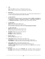
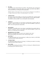
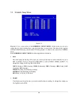
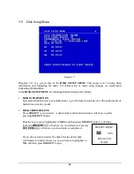
4. SECONDARY DNS

If your ISP provides you with a secondary DNS address, please set it in here.

NOTE:

Please complete all settings in the PPPoE Setup Menu before changing IP CONFIG to
PPPoE in the CONFIG options. If you make this change before completing PPPoE settings,
then the PPPoE function will not work.

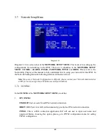
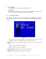
3.7.6 DDNS

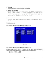
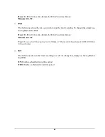
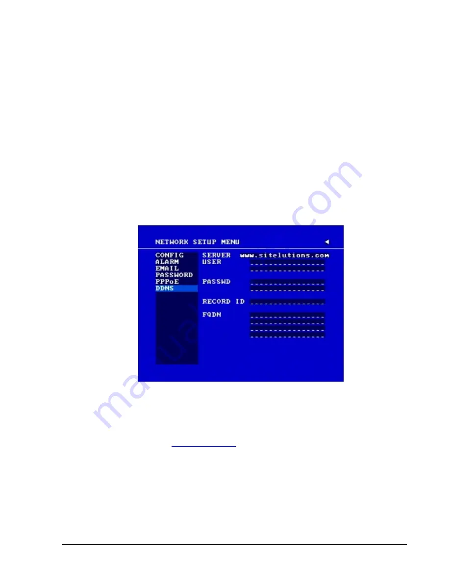
In the DDNS of the NETWORK SETUP MENU, we define:

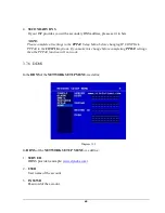
Diagram 3.15

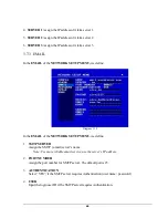
In DDNS of the NETWORK SETUP MENU, we define :

1. SERVER

DDNS provider (example:

www.dyndns.com

)

2. USER

User name of the account.

3. PASSWD

Password of the account.

Содержание 920

Страница 1: ...Instruction Manual E ED DR R1 16 64 40 0 1 16 62 20 0 9 92 20 0 ...

Страница 2: ...permission of the Everfocus Electronics Corporation Release Date August 2008 QuickTime is a registered trademark of the Apple Computer Inc Windows is a registered trademark of the Microsoft Corporation Linksys is a registered trademark of the Linksys Corporation D Link is a registered trademark of the D Link Corporation DynDNS is a registered trademark of the DynDNS org Corporation Other product a...

Страница 3: ... off and on the user is encouraged to try to correct the interference by one of the following measures Reorient or relocate the receiving antenna Increase the separation between the equipment and receiver Connect the equipment into an outlet on a circuit different from that to which the receiver is connected Consult the dealer or an experienced radio TV technician for help FCC Caution Any changes ...

Страница 4: ...rs identify the type of circuit intended cable type or relevant circuit characteristics Marking or Instruction CATUION Risk of Explosion if Battery is replaced by an Incorrect Type Dispose of Used Batteries According to the Instructions ...

Страница 5: ... network cable 21 2 6 2 Network connection through patch cable 22 2 6 3 Network system requirements 22 2 7 HARD DISK DRIVE INSTALLATION 22 2 8 FINAL INSTALL PROCESS 23 3 DVR MENU SETUP 24 3 1 TIME DATE SETUP MENU 25 3 2 CAMERA SETUP MENU 29 3 3 RECORD SETUP MENU 33 3 4 ALARM SETUP MENU 35 3 5 MOTION SETUP MENU 38 3 6 VIDEOLOSS SETUP MENU 41 3 7 NETWORK SETUP MENU 43 3 7 1 CONFIG 43 3 7 2 ALARM NET...

Страница 6: ...10 NETWORKING OVERVIEW 84 10 1 INTRODUCTION TO TCP IP 84 10 2 SUBNET MASKS 84 10 3 GATEWAY ADDRESS 84 10 4 VIRTUAL PORTS 85 10 5 PRE INSTALLATION 85 10 6 WHAT TYPE OF NETWORK CONNECTION DO YOU HAVE 87 10 7 SIMPLE ONE TO ONE CONNECTION 87 10 8 DIRECT HIGH SPEED MODEM CONNECTION 96 10 9 ROUTER OR LAN CONNECTION 98 11 LINKSYS PORT FORWARDING 101 12 D LINK PORT FORWARDING 105 13 EVERFOCUS DDNS SETUP 1...

Страница 7: ...SSION SETTING 133 15 2 REMOTE CONTROL PROTOCOL 134 APPENDIX A REMOTE CONTROL 139 APPENDIX B MOUSE INSTALLATION 140 APPENDIX C ALARM BOARD CONFIGURATION 143 APPENDIX D LAPSE MODE RECORDING TABLE 144 TROUBLESHOOTING 151 ...

Страница 8: ...ecifications are therefore subject to change without notice WARNING TO REDUCE RISK OF FIRE OR ELECTRIC SHOCK DO NOT EXPOSE THIS APPLIANCE TO RAIN OR MOISTURE Press the STOP key to stop playing back Note This is a class A product In a domestic environment this product may cause radio interference in which case the user may be required to take adequate measures ...

Страница 9: ...liance to water or moisture nor try to operate it in wet areas Take immediate action if the appliance becomes wet If this does happen turn the power off and refer servicing to qualified service personnel Moisture may damage the appliance and also cause electric shock Do not use strong or abrasive detergents when cleaning the appliance body Use a dry cloth to clean the appliance when it is dirty Wh...

Страница 10: ...y tub in a wet basement near a swimming pool in an unprotected outdoor installation or any area which is classified as a wet location Servicing Do not attempt to service this unit by yourself as opening or removing covers may expose you to dangerous voltage or other hazards Refer all servicing to qualified service personnel Power Cord Protection Power supply cords should be routed so that they are...

Страница 11: ...ds Up to 480 EDR1640 240 EDR1620 920 images per second 4 channel Audio Recording Capabilities local Motion Detection Capabilities Two 3 5 Hot Swap Hard Disks expendable to max 50 Hard Disks with EDA800S optional SCSI Interface for External Expanded Storage Ethernet Interface for Remote Network Viewing and Controlling RS232 RS485 for Remote Control Shuttle Jog Dial for Picture by Picture or Fast Sl...

Страница 12: ...nd 2x2 Zoom for Live and Playback Video Pause Yes Alarm Inputs 16 9 Alarm Inputs Alarm Outputs 4 Alarm Outputs Hard Disk Storage Two Hot Swappable 3 5 IDE Hard Disk Recording Rate 1640 Up to 480 IPS for NTSC 400 IPS for PAL 1620 920 Up to 240 IPS for NTSC 200 IPS for PAL Recording Mode Continuous Schedule Event Motion and Alarm recording Playback Rate Up to 60 50 Images per second for NTSC PAL Pla...

Страница 13: ...perating Temperature 0o C 40o C 32 104 Recording Rate NTSC PAL 1640 model D1 720x480 120 IPS Half D1 720x240 240 IPS CIF 360x240 480 IPS D1 720x576 100 IPS Half D1 720x288 200 IPS CIF 360x288 400 IPS 1620 model D1 720x480 60 IPS Half D1 720x240 120 IPS CIF 360x240 240 IPS D1 720x576 50 IPS Half D1 720x288 100 IPS CIF 360x288 200 IPS 920 model D1 720x480 60 IPS Half D1 720x240 120 IPS CIF 360x240 2...

Страница 14: ...ng and playing back 3 PLAY Press this key to start playing back 4 PAUSE Press this key to pause the playback picture 5 SEARCH Press this key to enter the SEARCH MENU 7 ENTER Press this key to enter items or jump to next subentry in the menu setting 8 DISPLAY Press this key to cycle through the display of channels and or status bar 6 COPY Press this key to enter the Copy Menu ...

Страница 15: ...an be moved through JOG ENTER key changes the scroll direction between horizontal and vertical Pressing the zoom key again switches the electronic zoom off In multiscreen mode Image orientation adjustment Use the JOG to adjust the image to the monitor type ENTER switches between horizontal and vertical adjustment Press the zoom key again to exit screen adjustment 9 SELECT On live view press this k...

Страница 16: ...change settings and values in subentries 16 System LEDs LEDs for system active HDD ALARM and LAN display 17 Channel Key 1 16 Press channel key CH1 CH16 to display that channel in full screen view 18 HDD LOCK Turn on HDD power and prevent HDD theft 19 Hard Disk Tray Hard Disk holder for HDD 20 HDD LED s LED s for HDD active power GREEN and data reading writing RED 21 LCD Panel To display Date and T...

Страница 17: ...er plug power source to AC 100 240V POWER MAIN MONITOR This connector is used for the main monitor display a number of different display modes may be selected for viewing CALL MONITOR This connector is used for the call monitor This monitor can only display a full screen MONITOR 3 4 For EDR1640 1620 Series VIDEO OUT 1 16 Top row BNC connectors for video looping out 1 16 VIDEO IN 1 16 Bottom row BN...

Страница 18: ...om row BNC connectors for video input 1 9 ALM INPUT Normal open or normal close type alarm signal inputs The Alarm Input can be selected as normal open N O or normal close N C input in the ALARM SETUP MENU When an alarm occurs alarm recording will automatically start ALM OUTPUT A built in relay offers 3 nodes which are ALM COM common ALM NO normal open and ALM NC normal close for external use Note...

Страница 19: ...put S Video Cascade 11 12 13 14 15 Cascade is designed for connecting a number of DVRs to one monitor You will be allowed to view and to control as many DVRs as you prefer from the same monitor simply switching the screen using a multi function keyboard controller Connect from Cascade out of the DVR to Cascade In of another with BNC connectors Repeat the same step for all your DVRs until you conne...

Страница 20: ...ing a FOCUS CAMERA in ALARM SETUP MENU is necessary Motion event Motion event only shows up when the camera s MOTION is enabled in MOTION SETUP MENU and the camera detects a motion Video loss event Video loss event only shows when the camera s VIDEOLOSS is enabled in VIDEOLOSS SETUP MENU and the camera signal is lost Sequence sign Sequence sign shows up when the display is in the sequence mode The...

Страница 21: ...ay back mode if you enable a status bar on the screen Please see DISPLAY 8th item of Front Panel Keypads There are three parts that will be shown play date play status and play time Play date The date on which the video was recorded Play status PAUSE when the video playback is paused P means normal play speed on the displayed disk number P means normal reverse play speed on the displayed disk numb...

Страница 22: ...sk space used To review the total amount of recording time please refer to the Disk Menu Chapter 3 9 3 Event The current last event that occurred 4 Current time The current time which is set in the TIME DATE SETUP MENU 5 Audio Ch Displays which audio channel is currently active This can be changed by turning the Jog wheel in the live camera mode 6 HDD Fan status No Disk only shows when no disk is ...

Страница 23: ...ified service personnel or system installers Please check accessories in the packaging before beginning installation Please refer to the following diagram for the basic wiring connections Note Monitors and Cameras must be purchased separately Diagram 2 1 Diagram 2 2 Chapter 2 ...

Страница 24: ...ideo sources must provide a 1 Vpp NTSC standard video signal When interconnecting transmission lines twisted pair fibre optics radio to the video inputs ensure the accurate receiver calibration The MAIN monitor may optionally be connected through a Y C S Video cable to achieve an improved image quality For local DVR operation MAIN monitor connection is compulsory Call and matrix monitors can be co...

Страница 25: ... EKB500 keyboard up to 255 EDR1640 1620 920 can be cascaded and administrated via one single main monitor Cascading is effected by connecting the DVRs CASCADE OUT to the CASCADE IN of the following DVR while the last CASCADE OUT is connected to the monitor input Diagram 2 4 Installation with 3 cascaded EDR and EKB 500 ...

Страница 26: ...e effected with audio coax cable and RCA plugs The output provides a max 500 mV to 10 KOhm line audio signal and may be connected to e g a monitor s audio input The direct connection of passive speakers is not supported AUDIO RECORDING FUNCTIONALITY Audio recording is activated deactivated in the RECORD menu for all channels Audio of all channels is always recorded together with each video and is ...

Страница 27: ...l telemetry control is provided by the optional EKB 500 keyboard Supported protocols EverFocus Pelco D Pelco P ED2200 2250 Diagram 2 6 Sample installation with 3 EPTZ1000 speed domes and EDA998 Diagram 2 7 Sample installation with 3 EPTZ1000 speed dome EDA998 and local EKB 500 operation Required DVR settings RS 485 receiver address in CAMERA menu RS 485 parameters and protocol in CONTROL menu ...

Страница 28: ...d in the ALARM menu Use either the 37 pin Sub D plug or the included adaptor board for connection Pin assignment adaptor board Pin assignment sub d board HOST PIN NAME PIN NAME 1 GND 21 GND 2 ALMIN1 22 ALM_NC1 3 ALMIN2 23 ALM_NO1 4 ALMIN3 24 ALM_COM1 5 ALMIN4 25 ALM_NC2 6 ALMIN5 26 ALM_NO2 7 GND 27 ALM_COM2 8 ALMIN6 28 GND 9 ALMIN7 29 ALM_NC3 10 ALMIN8 30 ALM_NO3 11 ALMIN9 31 ALM_COM3 12 ALMIN10 3...

Страница 29: ...LL OC output contact for signal HDD full switches to GND REC_IN Control contact for recording start SPARE_IN OUT System error output TTL level 5VDC indicates System Okay status The contact will switch to open state if one ore more of below listed events appears a HDD full If overwrite mode in RECORD menu is set to STOP b No HDD c Over temperature HDD d Power Loss e Cooler fan fault f Video Loss g ...

Страница 30: ...20 SPARE_IN N O Control input for playback function playback is active as long contact is closed NO contact alarm input connection NC contact alarm input connection Output relay in idle state ...

Страница 31: ... image transmission and network remote configuration This chapter doesn t go into basic networking For further information about router installation and internet connection please refer to the Chapter 10 through chapter 13 Physically two basic types of connection are possible 2 6 1 Direct PC connection through crossover network cable Diagram 2 9 The point to point connection of DVR and PC requires...

Страница 32: ...rn it to the lock position If this process is ignored the hard disk drive will not be detected Follow the previous steps for the second hard drive or second empty sleeve Both hard drives should be set to MASTER Otherwise they will not be detected Note A HDD should be installed before EDR1640 1620 920 is booted or the EDR1640 1620 920 will not detect a HDD until you reboot it with a HDD Please make...

Страница 33: ...drive installation you are ready to turn on the DVR Simply plug in the power source and turn the switch to the on position The POWER LED lights will light up if power is normal Once the system has finished loading the next step is to set up the menu options for the DVR Diagram 2 11shows 3 5 Hard Drive ...

Страница 34: ... find there are 12 setup option pages as follows Press MENU key to enter the MAIN MENU Press MENU key or click on the arrow at the top right corner of the screen with a mouse to go back to the previous menu Dial the Jog clockwise or counterclockwise to change subentry values Press the ENTER key to go to next subentry in a menu setting and press the CALL key to go to previous subentry in a menu set...

Страница 35: ...R and 24 HOUR format 2 TIME This field represents the current time on the DVR To change this simply use the Jog Dial on the DVR The Time is represented as follows Hour 00 23 1 12 if TIME FORMAT is 12 HOUR Minute 00 59 Second 00 59 3 DATE FORMAT This field represents the date format on the DVR To change this simply use the Jog Dial on the DVR There are three date formats which are YYYY MM DD MM DD ...

Страница 36: ...g to set the start week To set the start day of daylight saving time Dial the jog to set the start day To set the starting time change of daylight saving time Choose when the time changes from the old time FROM to the new time TO when daylight saving starts 7 END TIME To set the end time of daylight saving To set the end month of daylight saving time Dial the jog to set the end month To set the en...

Страница 37: ...se follow these steps a Go to a PC that is connected to the internet b Click on START RUN type cmd press OK c In the Dos Prompt type ping pool ntp org to find out the IP address of an NTP Server Diagram 3 3 10 TIME ZONE You can set the time zone that the DVR adjusts to when updating from the time server Atlantic Daylight Time subtract 3 hours from GMT Atlantic Standard Time subtract 4 hours from G...

Страница 38: ...ght Time subtract 8 hours from GMT Alaska Standard Time subtract 9 hours from GMT Hawaii Aleutian Daylight Time subtract 9 hours from GMT Hawaii Aleutian Standard Time subtract 10 hours from GMT 11 TIME UPDATE BY Once you enable the TIME SYNCHRONIZE you can select the synchronization frequency by DAY MONTH WEEK ...

Страница 39: ...9 A B C D E F G H I J K L M N O P Q R S T U V W X Y Z and an empty space 2 PTZ ID Select PTZ ID Address from 001 255 or OFF OFF is the same as 000 This ID must match the ID used by the PTZ camera To change this simply use the Jog Dial on the DVR 3 INSTALL COVERT For installation of camera select ON to enable a camera and OFF to disable it Please make sure to stop recording before making change to ...

Страница 40: ...KB 13 7KB BASIC 10 15KB 16 72KB STANDARD 11 86KB 19 56KB HIGH 14 72KB 24 63KB Average size per image SUPERIOR 18 60KB 30 05KB 720x240 Video Source Simple Complex LOWER 3 53KB 7 82KB LOW 3 87KB 8 36KB BASIC 4 21KB 8 9KB STANDARD 4 92KB 9 54KB HIGH 5 62KB 10 17KB Average size per image SUPERIOR 6 41KB 12 89KB 360x240 Video Source Simple Complex LOWER 1 76KB 4 56KB LOW 1 87KB 4 87KB BASIC 1 97KB 5 46...

Страница 41: ...d you need to disable all current record actions and then turn them back on ACTION Set ON to activate motion action on a Time Period Set OFF to disable motion action on a Time Period This setting correlates closely with Motion Setup If motion setting is disabled motion detection will not function regardless if Action in Camera Setup Menu is ON or OFF However if Motion setting is enabled then motio...

Страница 42: ...s setting from a camera to other cameras In order to quickly copy the setting from one camera to other cameras we provide a copy function for camera settings Highlight the desired camera from the list on the left and then press COPY COPIED will show up in the top right corner of the screen Dial the Jog to the camera you would like to copy to and then press SEARCH to paste The previous settings of ...

Страница 43: ... follows 1 RECORD AUDIO YES Audio will be recorded when machine is recording and a microphone is present NO Audio will not be recorded when machine is recording 2 TIME STAMP ON The time stamp will show on the video and picture when recording OFF The time stamp will not show on the video and picture when recording 3 TIME STAMP POSITION BOTTOM The time stamp will show on the bottom TOP The time stam...

Страница 44: ...1620 920 360x240 480 IPS EDR1640 or 240 IPS EDR1620 920 6 RECORD MODE REWRITE Continue recording Disk will begin overwriting when it is full STOP Stop recording when disk is full 7 AUTOWRITE WITHIN You can set DVR to automatically overwrite after the selected number of days If you do not wish to use this function simply select 0 8 PRE ALARM RECORDING Select YES to enable pre alarm recording functi...

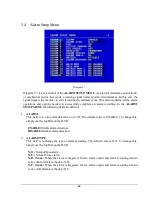
Страница 45: ... are defined 1 ALARM This field is to turn alarm detection on or off The default value is ENABLE To change this simply use the Jog Dial on the DVR ENABLE Enable alarm detection DISABLE Disable alarm detection 2 ALARM TYPE This field is to change the type of alarm recording The default value is N O To change this simply use the Jog Dial on the DVR N O Normal Open alarm N C Normal Close alarm N O Tr...

Страница 46: ...e alarm recording screen change buzzer and output contact will last Adjustable from 1 99 seconds TRANSPARENT Continuous recording screen change buzzer and output contact for a triggered alarm event 7 ALARM OUTPUT This will transmit a signal to another device The setting of alarms are NONE not activated 1 output signal 1 transmits 2 output signal 2 transmits 3 output signal 3 transmits and 4 output...

Страница 47: ...call monitor when an alarm occurs according to sequence duration set in Camera Setup Menu ACTIVE CAMERA Display the active camera in full screen mode to the call monitor when an alarm occurs 13 SUMMARY Dial Jog to change items in the SUMMARY table All alarms statuses are shown in SUMMARY tables These tables are for checking overall alarm statuses not for changing them ...

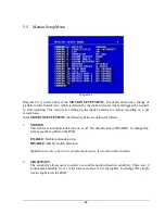
Страница 48: ...MENU the following fields are defined as follows 1 MOTION This field is to turn motion detection on or off The default value is DISABLE To change this simply use the Jog Dial on the DVR ENABLE Enable motion detection DISABLE Disable motion detection Note Motion only works in live and playback modes It is invalid while in menus 2 SENSITIVITY The sensitivity allows users to adjust to a suitable moti...

Страница 49: ...t in the NETWORK SETUP MENU 7 ALARM NETWORK YES Enable alarm network when an alarm occurs NO Disable alarm network when an alarm occurs 8 BUZZER Audible buzzer when motion is detected ENABLE To enable a motion buzzer DISABLE To disable a motion buzzer 9 MOTION DELAY Select motion delay time from 0 7 level 10 MAIN MON Display on main monitor when motion occurs NO CHANGE No change on the main monito...

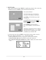
Страница 50: ...f you forget the motion grid commands Press CALL to display a hint window shown below In the motion edit mode The default motion area of each camera is entire screen which displays in light green Press COPY or left click the mouse to start setting an area Use the JOG Dial to move the cursor Press ENTER to switch between vertical and horizontal movement Press SEARCH to end and enable the area or pr...

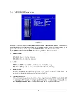
Страница 51: ...tion DISABLE Disable video loss detection 2 LOG YES Select YES if you wish to record Video Loss Events in the Log NO Select NO if you do not wish to record Video Loss Events in the Log 3 DURATION Duration of VIDEOLOSS buzzer ranges from 1 sec to 99 seconds The default value is 5 seconds To change this simply use the Jog Dial on the DVR 4 ALARM OUTPUT This will transmit a signal to another device T...

Страница 52: ...TUP MENU 6 BUZZER Audible alarm buzzer ENABLE To enable a VIDEOLOSS buzzer DISABLE To disable a VIDEOLOSS buzzer 7 ALARM NETWORK YES Enable alarm network NO Disable alarm network 8 SUMMARY All video loss s statuses are shown in SUMMARY tables These tables are for checking video loss overall statuses but not for changing them ...

Страница 53: ... the following fields are defined as follows Note Since every Network Configuration is different please contact your Network Administrator or ISP for how to assign those IP addresses and port numbers 3 7 1 CONFIG In the CONFIG of the NETWORK SETUP MENU we define 1 IP CONFIG FIXED IP User can set a fixed IP for network connection DHCP DHCP server in LAN will automatically provide the IP for network...

Страница 54: ...in the network To change this simply use the Jog Dial on the DVR When DHCP is selected the DHCP server will assign this value automatically 5 DNS SERVER This field is to set the DNS server for your network so the DVR will be recognized within the network To change this simply use the Jog Dial on the DVR When DHCP is selected the DHCP server will assign this value automatically 6 REMOTE RELAY CONTR...

Страница 55: ... our Control Management System PowerCon4 In the ALARM of the NETWORK SETUP MENU we define Diagram 3 11 Note Since every Network Configuration is different please contact your Network Administrator or ISP for how to assign those IP addresses and port numbers 1 PROTOCOL Select which communication protocol with Alarm servers or Alarm receiving clients TCP communicate with client via TCP protocol UDP ...

Страница 56: ... Diagram 3 12 In the EMAIL of the NETWORK SETUP MENU we define 1 SMTP SERVER Assign the SMTP e mail server s name Note For more reliable email service use the server s IP address 2 PORT NUMBER Assign the port number for SMTP server The default port is 25 3 AUTHENTICATION Select YES if the SMTP server requires Authentication user name password 4 USER Input the login user ID if the SMTP server requi...

Страница 57: ...ack by opening DVRViewer exe which can be downloaded from the DVR s Network Viewer or from the Copy Menu 7 SENDER EMAIL ADDR Input sender s e mail address so that receiver can recognize the sender when an event message is sent out 3 7 4 PASSWORD In the PASSWORD of the NETWORK SETUP MENU we define Diagram 3 13 In the PASSWORD of the NETWORK SETUP MENU we define Name Password Level This category is ...

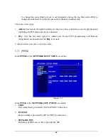
Страница 58: ...a if one is connected 2 Play User has the same rights as Admin user Except PTZ programming and Remote configuration are not authorized to Play level users 3 Live Allows user only to view live video 3 7 5 PPPOE In the PPPOE of the NETWORK SETUP MENU we define Diagram 3 14 In the PPPoE of the NETWORK SETUP MENU we define 1 USER User name that is provided by ISP for PPPoE Connection 2 PASSWD Password...

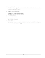
Страница 59: ...ing IP CONFIG to PPPoE in the CONFIG options If you make this change before completing PPPoE settings then the PPPoE function will not work 3 7 6 DDNS In the DDNS of the NETWORK SETUP MENU we define Diagram 3 15 In DDNS of the NETWORK SETUP MENU we define 1 SERVER DDNS provider example www dyndns com 2 USER User name of the account 3 PASSWD Password of the account ...

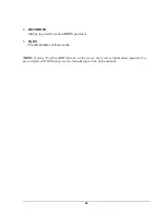
Страница 60: ...tag used by certain DDNS providers 5 FQDN The domain name of this account NOTE If using EverFocusDDNS com as the server there is less information required For more details on DDNS setup see the Networking section of the manual ...

Страница 61: ...lds are defined as 1 DAY This field represents the day of the week you wish to set the timer record for Initially it is set to DLY as default You may choose from MON SUN as well as WDAY WEND and DLY To change this simply use the Jog Dial on the DVR MON Monday TUE Tuesday WED Wednesday THU Thursday FRI Friday SAT Saturday SUN Sunday WDAY Weekday from Monday to Friday WEND Weekend Saturday and Sunda...

Страница 62: ... Dial on the DVR Hour 0 23 in 24 hour time format 1 12 in 12 hour time format Minutes 00 59 Note To record a 24 hour period set 12 00am 12 00 am for 12 hour format 00 00 00 00 for 24 hour format 4 SET This field is used to turn the timer recording on or off To change this simply use the Jog Dial on the DVR ON Enable a scheduled record time period OFF Disable a scheduled record time period ...

Страница 63: ... disks in intervals of 4 The total number of hard drives varies by model 2 DISK VIDEO DELETE Press SELECT to start delete A delete disk confirmation window will show up after pressing SELECT button Dial the Jog to move highlighter to YES and then press SELECT button a deleting indicator DELETE will show up An indicator of success SUCCESS will show up when delete is completed If you do not want to ...

Страница 64: ...US or FAHRENHEIT for thermometric scale of the disk 4 NO Shows the hard drive number The number of disks displayed may vary depending on the model 5 SIZE Storage capacity of the hard drive 6 C or F Current temperature of the hard drive in Celsius or Fahrenheit degrees 7 START END TIME Shows the date and time range stored on the hard drives ...

Страница 65: ...DVR There are six different speeds 2400 BPS 4800 BPS 9600 BPS 19200 BPS 38400 BPS and 57600 BPS The default setting from the factory is 9600 BPS To change this simply use the Jog Dial on the DVR 2 RS232 Stop Bit This field is to set the stop bit for the RS232 connection There are two different stop bits 1 or 2 The default in the DVR is set to 1 To change this simply use the Jog Dial on the DVR 3 R...

Страница 66: ...ent stop bits 1 or 2 The default in the DVR is set to 1 To change this simply use the Jog Dial on the DVR 3 RS485 Parity This field is to select the parity level at which you will be connected You can choose between None Odd or Even parity levels Default is set to none To change this simply use the Jog Dial on the DVR 4 RS485 Data Bit This field is the data bit at which you will be transferring Th...

Страница 67: ...buzzer To change this simply use the Jog Dial on the DVR ENABLE To enable a buzzer when the fan does not work DISABLE To disable fan buzzer 2 ALARM OUTPUT This will transmit a signal to another device The setting of alarms are NONE not activated 1 output signal 1 transmits 2 output signal 2 transmits 3 output signal 3 transmits and 4 output signal 4 transmits To change this simply use the Jog Dial...

Страница 68: ...zer ENABLE To enable a buzzer when HDD s temperature is higher than the temperature set in SET TEMPERATURE DISABLE To disable HDD TEMP Buzzer 2 ALARM OUTPUT This will transmit a signal to another device The setting of alarms are NONE not activated 1 output signal 1 transmits 2 output signal 2 transmits 3 output signal 3 transmits and 4 output signal 4 transmits To change this simply use the Jog Di...

Страница 69: ...tings can be set in the NETWORK SETUP MENU 6 STOP RECORD YES Stop recording when HDD s temperature is overheated NO Will not stop recording even when HDD s temperature is overheated 7 SET TEMPERATURE When HDD s temperature is higher than the temperature set here all other active settings in HDD TEMP will take effect BUZZER ALARM OUTPUT ALARM DURATION NETWORK ALARM SEND EMAIL STOP RECORD The defaul...

Страница 70: ...vice The setting of alarms are NONE not activated 1 output signal 1 transmits 2 output signal 2 transmits 3 output signal 3 transmits and 4 output signal 4 transmits To change this simply use the Jog Dial on the DVR 3 ALARM DURATION The length of time the buzzer remains active This can be set from 1 sec to 99 seconds or permanent The default value is 5 seconds 4 NETWORK ALARM YES To enable network...

Страница 71: ...ble a buzzer when HDD is full DISABLE To disable HDD Full buzzer 2 ALARM OUTPUT This will transmit a signal to another device The setting of alarms are NONE not activated 1 output signal 1 transmits 2 output signal 2 transmits 3 output signal 3 transmits and 4 output signal 4 transmits To change this simply use the Jog Dial on the DVR 3 ALARM DURATION The length of time the buzzer remains active T...

Страница 72: ...RK ALARM YES To enable network alarm NO To disable network alarm 5 SEND EMAIL YES Send an email when HDD is full NO Will not send an email when HDD is full The email settings can be set in the NETWORK SETUP MENU ...

Страница 73: ... system to properly detect the video format 3 LOAD SAVE CONFIGURATION YES Turn the Jog to enter the selection window There are 4 options available CANCEL DEFAULT LOAD and SAVE Use the Jog Wheel to scroll through these options and press SELECT to confirm your choice CANCEL exits from selection window DEFAULT restores the factory default values LOAD uploads saved DVR configuration settings from USB ...

Страница 74: ...e disk in Disk Setup Menu 5 LANGUAGE System can be set in different languages The available languages depend on the country or area subject to change Please consult your sales representative for the most updated information 6 QUICK PLAY Allows the user to automatically play back the most recent video after pressing the PLAY button ON Enable quick play Video starts playing from the set quick play t...

Страница 75: ...access levels and the default none access level The following chart shows the rights of each level User Level and Right LEVEL 3 LEVEL 2 LEVEL 1 NONE ACCESS ADMINISTRATOR OPERATOR GENERAL DISPLAY OK OK OK OK MODE OK OK OK OK ZOOM OK OK OK OK SELECT OK OK OK NO SEQ OK OK OK NO CALL OK OK NO NO MENU OK NO NO NO COPY OK NO NO NO SEARCH OK NO NO NO PLAY OK NO NO NO STOP OK NO NO NO REC OK NO NO NO PAUS...

Страница 76: ...cording immediately When REC is pressed the pictures being monitored will be recorded in the HDD The recording quality and recording speed can be set in the CAMERA SETUP MENU To set the target camera for a particular recording speed IPS when using the instant record method apply the changes to the last Time Period TP row labeled N A R01 sign appears in the record status bar The number following R ...

Страница 77: ... the event recording is enabled the DVR will start an event recording when an event occurs For instance when motion activity or alarm action is detected by the DVR it will begin recording at the specific IPS set in the Event column In order to start an event recording you MUST perform the following 1 First enable each event alarm or motion in its respective menu For example you can enable motion o...

Страница 78: ...ding speed IPS of the camera in the time period TP section Diagram 4 3 3 Once the event and record and speed are set you need to activate Instant Recording or set a time period TP in the SCHEDULE SETUP MENU You can refer to the SCHEDULE SETUP MENU for time period configurations Chapter 3 8 ...

Страница 79: ...ill not take effect until recording is stopped completely 4 4 ALARM INPUT RECORDING Input trigger DVR provides a record function which is triggered by external signal via the 19th pin of the ALARM INPUT OUTPUT port When the record input signal is triggered constantly DVR will start to record according to the speeds set on Time Period TP N The system will stop recording when the record input signal...

Страница 80: ...The DVR is duplex which means you can record and playback the same time Press STOP key to stop playing back 3 Fast Forward Reverse Playback While in playback turn the Shuttle dial clockwise to begin fast forward playback Turn the Shuttle dial counterclockwise to begin fast reverse playback The speed will be shown on the status bar of the bottom screen The available speeds are 2 4 6 8 16 32 and 600...

Страница 81: ... 4 1 8 1 16 and 1 32 You can either manually hold the shuttle dial in the position or press ENTER while holding the dial to lock the speed that is desired 5 2 Search Playback Press SEARCH key to enter the SEARCH Menu In the SEARCH MENU Dial the Jog clockwise or counterclockwise to change subentry values Press ENTER key to go to next subentry in search menu setting and press the CALL key to go to p...

Страница 82: ...lect the start date time you want to search Then select the camera number and Disk Number to be searched Lastly press SELECT or the tilt wheel of mouse to start search Note If there is no video stored in the date time specified then the image will show the end of the last playback and the display time on the status bar will show ...

Страница 83: ... total pages shows in the top right corner Dial Shuttle clockwise or press COPY to move to the next page dial Shuttle counterclockwise or press CALL to move to the previous page If you would like to jump to a specific page directly you can press Search then dial Jog to the page and press Enter Dial the Jog to scroll through events on the list When the desired event is highlighted press ENTER to pl...

Страница 84: ...annel number PH Physical Head beginning of physical hard drive space PL a Power Loss event RTn a power ReTurn event in schedule recording mode n TP1 8 RTN a power ReTurn event in Normal instant recording mode RUn Remote User login through Internet Explorer n 1 6 user number Tn begin schedule recording mode n TP 1 8 TN begin Normal instant recording mode Vn a Video loss event n the channel number D...

Страница 85: ...how to copy a still image or movie from the recorder Insert the USB pocket drive into the USB slot on the front panel USB SLOT Digital Video Recorder allows users to copying image video from a selected camera or copying DVR Viewer which is the image video player The camera title will be displaying at the top of the screen Chapter 6 COPY Press COPY key to enter the Copy Menu ...

Страница 86: ...lect ALL cameras while you are recording DVR will stop recording temporarily until copy process is terminated 4 START DATE TIME The start time of video you want to copy END DATE TIME The end time of video you want to copy 5 SIZE OF SELECTED IMAGE __ MB PRESS PLAY TO ESTIMATE The system can estimate the file size of the selected image you wish to copy Simply press PLAY key after you have selected s...

Страница 87: ... to download the DVR Viewer file Insert a USB pocket drive into the DVR Press COPY button to enter the Copy Menu In the Copy Menu choose Viewer at the top of the screen Then press SELECT button to copy the viewer to the USB 2 Remove the USB and insert it into your computer 3 Open up My Computer in Windows Open the Removable Drive You will see the files you archived as well as the DVR Viewer you ju...

Страница 88: ...ay on the call monitor Press SEQ key or Middle wheel of mouse to switch the sequence status ON or OFF 2 OSD Channel name display on the call monitor Press DISPLAY key or right click the mouse to switch the OSD status ON or OFF 3 CAMERA The current display camera in the call monitor Press Channel NO or slide wheel of mouse to set display camera 4 Sequence dwell time setting Turn the jog dial with S...

Страница 89: ...79 Diagram 7 2 Dial jog to set sequence dwell time for each camera on matrix monitor 1 4 Sequence dwell time can be set from 00 to 99 seconds Press Enter Call key to go next previous selection ...

Страница 90: ... The current camera cannot be changed 2 BRIGHTNESS The brightness percentage of the current camera from 0 to 100 3 CONTRAST The contrast percentage of the current camera from 0 to 100 4 COLOR The color percentage of the current camera from 0 to 100 5 SHARPNESS By turning SHARPNESS ON the image will become sharper and clearer in live mode This option is suitable for indoor use Chapter 8 ...

Страница 91: ... After finished setting press SELECT or MENU key to save and exit the screen 1 In a full screen display pressing ZOOM button from front panel will allow you to zoom in the image Dial Jog to move upward downward leftward or rightward of the zoomed in image Press ENTER key to change direction between or Press ZOOM button again to exit 2 In a multi screen display pressing ZOOM button from front panel...

Страница 92: ...82 8 1 Mode Button Press MODE to switch 4 7 9 10 13 16 and PIP picture in picture displays for Live and Playback mode ...

Страница 93: ... all schedules off then exit completely from Menu 5 Once you have stopped any type of recording on the DVR you are ready to upgrade 6 Press the MENU button and use the Jog Dial to go to System Menu 7 Press ENTER until System Upgrade is highlighted then change NO to YES using the Jog wheel 8 Choose YES again and press SELECT to confirm 9 You will see Updating 1 3 at the bottom left of the screen St...

Страница 94: ... using the range of addresses that are reserved for private local area networks this range of IP addresses usually begins with 192 168 The first three octets of an IP address should be the same for all computers in the local area network For example if a total of 253 computers exist in a single LAN the IP addresses could be assigned starting with 192 168 1 x where x represents a number in the rang...

Страница 95: ... by the Web browser to connect to the Web server Normally a Web site uses port number 80 and this number need not be included with the URL although it can be In IP networking port numbers can theoretically range from 0 to 65535 Most popular network applications though use port numbers at the low end of the range such as 80 for HTTP This could be similar to the front door of your house Without the ...

Страница 96: ...ity of your computer and can easily connect with it That way you can host a website email server or other type of server connection Everfocus suggest using a static IP address If your Internet provider does not offer a static IP address you have the option to use a dynamic IP address This will be explained in more detail later on in the chapter Do you have a dynamic IP address ______________ A Dyn...

Страница 97: ...ed modem connection is a network connection from the modem directly to a computer or in this case the DVR 3 Router or LAN Connection A local area network connection either requires a router or a pre existing LAN connection Typically this type of connection is the most commonly used application A router allows multiple computers and DVR s to access each other as well as the Internet It assigns diff...

Страница 98: ...rt on the back of the recorder and the other into the network card on the back of the computer Now Log into the Everfocus DVR menu and using the jog dial from the previous chapter go to the Network Setting Menu Assign an IP address of 192 168 001 003 to the DVR a Subnet mask of 255 255 255 000 and a default gateway of 192 168 001 001 The next step is to get the computer onto the same network to do...

Страница 99: ...89 ...

Страница 100: ...90 ...

Страница 101: ...91 ...

Страница 102: ...nce you have reached this point click ok and restart both the computer and the digital recorder To access the DVR from the computer simply open Internet Explorer and in the address bar type http 192 168 1 3 ...

Страница 103: ...ing the web page it installs the activeX control that allows you to run the application needed for that web page Such is the case for the DVR The EDR series of recorders require that ActiveX be enabled on Internet Explorer in order to fully view the cameras If the ActiveX options on Internet Explorer are not on then the cameras will not be displayed Enabling ActiveX Open the Control Panel from the...

Страница 104: ...94 ...

Страница 105: ...n ActiveX controls and plug ins Enable Script ActiveX controls Marked safe for scripting Enable If you are still not able to load the active X control change RESET CUSTOM SETTINGS to low and then click on RESET Once Enabled Click on OK on the Security Settings window Then click on apply on the Internet Options window and finally click OK ...

Страница 106: ...p is to purchase or make a straight through cable We recommend purchasing one if you have never made a straight through cable Please remember you can not use a cross over network cable for this application Once you have a straight through cable plug one end into the LAN port on the back of the recorder and the other into the high speed modem Cat 5 Straight Through Cable Internet Hi speed modem DVR...

Страница 107: ... default gateway of the internet service provider Note If you have a dynamic IP address this type of connection can work directly through the DVR directly The DVR can be used as a DHCP client Therefore it can receive a dynamic IP address Once you have reached this point click ok and restart both the computer and the digital recorder To access the DVR from a computer simply open Internet Explorer a...

Страница 108: ...traight cable Diagram 10 3 Connection Procedure The First step is to purchase or make a straight through cable We recommend purchasing one if you have never made a straight through cable Please remember you can not use a cross over network cable for this application Cat 5 Straight Through Cable Internet Hi speed modem DVR Router ...

Страница 109: ...an IP address of 192 168 000 050 to the DVR a Subnet mask of 255 255 255 000 and a default gateway of 192 168 000 001 If you have a pre existing LAN Go to a Computer on the pre existing network and do the following o Go to Start then Run and type cmd and click on OK Then hit enter type ipconfig and press enter this will give you the information you will need Use the prior step to assign an IP addr...

Страница 110: ... through the DVR s Network Menu Setup Note If you wish to have multiple users log into the DVR please open a range for the control and data ports on your router For example if you would only like 4 clients to connect to the DVR open 1600 1603 and 37260 37263 If you have a Dynamic IP address and have open the ports simply go to Chapter 13 to Configure DDNS Once you have reached this point and you h...

Страница 111: ...uter s default IP address 192 168 1 1 in the Address field Then press Enter A password request page will appear Non Windows XP users will see a similar screen Leave the User Name field blank The first time you open the Web based Utility use the default password admin You can set a new password from the Administration tab s Management screen Click the OK button to continue The first screen that app...

Страница 112: ...ed Internet applications Specialized Internet applications are any applications that use Internet access to perform functions such as videoconferencing or online gaming Some Internet applications may not require any forwarding To forward a port enter the information on each line for the criteria required Descriptions of each criterion are described here ...

Страница 113: ...ends the range under End Protocol Enter the protocol used for this application either TCP or UDP or Both IP Address For each application enter the IP Address of the PC running the specific application Enable Click the Enable checkbox to enable port forwarding for the relevant application Change these settings as described here and click the Save Settings button to apply your changes or Cancel Chan...

Страница 114: ...different port to access the DVR through the DVR s Network Menu Setup please open those specific ports in this section of the router Note If you wish to have multiple users log into the DVR please open a range for the control and data ports on your router For example if you would only like 4 clients to connect to the DVR open 1600 1603 and 37260 37263 The following is the address you would type ht...

Страница 115: ...rstand we do not support this product and will not give tech support on it If you need Technical support on this router you must call D Link This Chapter is to offer some help to the installer and end user nothing more The next step is to open ports within your router Go to Virtual Server in the router Chapter 12 ...

Страница 116: ... the WAN Wide Area Network that will be providing the virtual services If you have a Web server that you wanted Internet users to access at all times you would need to enable it Simply place a Private IP The server computer in the LAN Local Area Network that will be providing the virtual services If you have a Web server that you wanted Internet users to access at all ...

Страница 117: ...your router Open virtual ports in the router o EDR Ports to open 80 1600 1601 1602 1603 37260 37261 37262 37263 Note If your Internet service provider blocks port 80 and you are using a different port to access the DVR through the DVR s Network Menu Setup please open those specific ports in this section of the router Note If you wish to have multiple users log into the DVR please open a range for ...

Страница 118: ...Focus DDNS server Set up the Network Menu according to the instructions detailed in the Networking chapter Go to the website http everfocusddns com and check for an available name In DVR s Network Menu go to DDNS Choose everfocusddns com for the Server and put in your chosen name for DVR Name Chapter 13 ...

Страница 119: ...r You should see the word Success at the bottom of the screen If you see Could Not Find Server instead double check your network settings until you get Success You should now be able to connect by typing in the host name you created Example http hostname everfocusddns com ...

Страница 120: ... page will appear on the screen similar to the one shown above User must enter a user name and password to access the recorder You can find your user name and password in the Network setting menu of your DVR The Default user name and password are admin and 11111111 Remote user ID and Password can be found in the Network Menu Then click on the submit button and you will be logged into your recorder...

Страница 121: ...K to close the window After a few seconds you should see a screen like the one below If you do not see a yellow bar like the one the arrow is pointing at your security settings may be too high If so go to the section labeled Enabling ActiveX Controls Right click on the yellow bar and select Install ActiveX Control ...

Страница 122: ...112 Install the MP4DVR file when prompted to do so Type in the username and password and click Login to view the cameras Default username admin Default password 11111111 ...

Страница 123: ...ecessary if you DO NOT see the yellow ActiveX bar at the top of your browser screen At the top of the Internet Explorer Window click on Tools then select Internet Options Click the Security tab at the top of the window then choose Custom Level near the bottom ...

Страница 124: ... prompting for ActiveX controls Binary and script behaviors Display video and animation on a webpage that does not use external media player IE7 only Run ActiveX controls and plug ins Script ActiveX controls marked safe for scripting Prompt Download signed ActiveX controls Download unsigned ActiveX controls Disable Initialize and script ActiveX controls not marked as safe Click OK and then choose ...

Страница 125: ...k at the DVR Viewer screen Click the Refresh button to reload the page Install the MP4DVR file when prompted to do so Type in the username and password and click Login to view the cameras Default username admin Default password 11111111 ...

Страница 126: ...tion is not accessible in the current mode The followings are a brief description for each of the icons 1 REV PLAY Reverse Video Playback 2 STOP Press this key to stop Playback and return to Live mode 3 PLAY Normal Video Playback 4 STEP BACKWARD Move one frame back while paused 5 PAUSE To pause the Video Playback display 6 STEP FORWARD Move one frame forward while paused 8 18 7 19 11 17 9 20 10 16...

Страница 127: ...ew 14 Quad screen view 15 Nine split screen view 16 Sixteen split screen view 17 If you right click on a camera screen a drop down list of available cameras appears Click on the desired camera to display it in that view screen 18 There are 4 main functions of Remote Viewer SEARCH PTZ ARCHIVE and CONFIG SEARCH section allows you to search by event or by time PTZ section allows you to control PTZ ca...

Страница 128: ...ote site Select audio source 1 2 3 4 or OFF to disable this function 23 Audio Broadcast This function is designed to transmit audio through a microphone to DVR that has speaker device installed Keep this button pressed whenever you need to do audio broadcasting Release this button to stop transmitting audio to DVR 24 Relay Output Press the button to trigger relay output 25 OSD Press to show OSD in...

Страница 129: ...d The buttons on the left hand side are to decrease the value whereas those on the right hand side are to increase the value 2 Move the slide bar between the buttons to change Month Day Hour Minute and second to be searched Move the slide bar to the left to decrease the value or to the right to increase the value 3 Enter Month Day Hour Minute and second directly in display bar Press OK to start se...

Страница 130: ...utton to refresh the event list 4 All events of the selected type will be displaying along with Date Time event type represented by a capital letter camera number represented by a number For example M02 is a motion event from camera 2 5 When there is a sign in front of the date with page number at the end double click to show all the events of that page 6 Press Play button to playback the selected...

Страница 131: ...he subject 6 You can turn on the Iris by pressing Open or turn it off by pressing Close 8 Click to Preset Point helps you to define the preset point you want the camera to look at Press Set to confirm Clear to delete or Jump to jump to a specific point 9 Auto Pan is to define the speed of PTZ camera when moving horizontally Choose from Slower Slow Normal Fast to Faster Press Run to start or Stop t...

Страница 132: ...at you wish to archive from 4 Start Select the start time of the archived video 5 End Select the end time of the archived video There are 3 ways to search Start or End time to be archived First press 1 Press on the M button to change the Month to be searched D for day h for hour m for minute and s for second The buttons on the left side are to decrease the value whereas those on the right side are...

Страница 133: ...inute and second directly in display bar 4 Press OK to select time 6 Press ARCHIVE button to start archiving An arv file will be saved 7 Press STOP button if you wish to cancel archiving 8 Check Display video if you wish to display what you are archiving on the screen while archiving file at same time In order to play the archived EDR MPEG4 Files arv you will need to download viewer 1 Press Downlo...

Страница 134: ...124 2 Select Run or Save the file 3 Open the DVRViewer exe for loading the archived EDR MPEG4 Files arv ...

Страница 135: ...e rate will be automatically calculated It is suggested to use the calculated Recording Frame Rate although it is possible to change this value 2 If you wish to save the audio recorded please select Audio ON so that the audio can be transferred to AVI file Otherwise select Audio OFF Note If you are unable to play AVI file downloaded from DVRViewer your PC may require a video codec The codec can be...

Страница 136: ...n each option to go to the settings for that page When you finish making changes on a screen press Apply to save the settings Press Reset to display the DVR s current menu settings The settings you make remotely in this page are virtually the same as the way you set up the DVR itself except for as noted in the following pages ...

Страница 137: ...ick to decrease Year value to increase Year value 3 Click to decrease Month value to increase Month value 4 Click on the selected date directly 5 Click on the Hour Minute Seconds to change Time value Up arrow for increasing and Down arrow for decreasing the value This is also used to change between Am and Pm 6 Finally click Apply to confirm setting ...

Страница 138: ...128 CAMERA setup menu RECORD setup menu ALARM setup menu ...

Страница 139: ...ed for motion green squares are enabled 2 Click and hold the mouse to begin selecting squares in the motion grid 3 Drag the mouse to highlight the desired area 4 The selected area will switch to the opposite color 5 Click Apply to save the changes VIDEO LOSS setup menu ...

Страница 140: ...guration Settings can not be changed remotely These must be changed in the DVR s Network Menu NETWORK 2 setup menu After saving changes to the account password or level the changes will take effect the next time you log in to the network viewer ...

Страница 141: ...131 SCHEDULE setup menu CONTROL setup menu ...

Страница 142: ... the menu or make changes at the DVR while this process is happening 4 When the update is complete the DVR will reboot automatically 5 Once Load System has finished the system s software will be updated You will need to refresh the network viewer for the changes to take effect Load Save Configuration 1 Clicking Save will open a Save File window 2 Select the folder you wish to save the configuratio...

Страница 143: ...onnector on DVR back panel is shown in the following picture 15 1 Transmission Setting There are 6 different speeds that can be used to transmit instruction or information through the RS485 port on the device 1200 baud 2400 baud 4800 baud 9600 baud 19200 baud and 3840 baud The default setting from the factory is 9600 baud Chapter 15 Pin 3 RS 485 Pin 6 RS 485 1 2 3 4 5 6 7 8 ...

Страница 144: ... EDR ID 5 0x85 length 0x00 Receiver ID high byte 0x05 Receiver ID low byte 0x4B OPcode key 0x08 DATA1 Rec keycode 0x5D checksum Example2 A packet that send PAUSE key to EDR ID 4999 0x85 length 0x27 Receiver ID high byte 0x07 Receiver ID low byte 0x4B OPcode key 0x0C DATA1 Pause keycode 0x0A checksum Example3 A packet that send PLAY key to all EDR broadcast 0x85 length 0x7f Receiver ID high byte 0x...

Страница 145: ...r ID high byte Receiver ID low byte Opcode Byte Data Byte1 Data Byte2 Data Byte3 Checksum Byte 2 2 Length Byte This Length Byte is also a prefix Bit7 must be 1 EX 0x87 this packet has 7 bytes length not included Length byte itself 2 3 Receiver ID 1 Individual receiver ID Decimal 14bit binary value Hbyte Lbyte Receiver ID 0 0000000 0000000 00 00 ID 0 ...

Страница 146: ...128 129 0000001 0000001 01 01 ID 129 255 0000001 1111111 01 7f ID 255 256 0000010 0000000 02 00 ID 256 511 0000011 1111111 03 7f ID 511 16382 1111111 1111110 7f 7e ID 16382 2 Broadcast ID Decimal 14bit binary value Hbyte Lbyte Receiver ID 16383 1111111 1111111 7f 7f All EDR connect to RS485 RS232 2 4 Opcode Byte Data bytes 2 4 1 OPcode OPcode Data1 Function ...

Страница 147: ...0 0x03 CH4 0x11 SHUTTLE 1 0x04 MODE 0x12 SHUTTLE 2 0x05 ZOOM 0x13 SHUTTLE 3 0x06 SEQ 0x14 SHUTTLE 4 0x07 MENU 0x15 SHUTTLE 5 0x08 REC 0x16 SHUTTLE 6 0x09 REV PLAY 0x17 SHUTTLE 0 0x0A STOP 0x18 SHUTTLE 1 0x0B PLAY 0x19 SHUTTLE 2 0x0C PAUSE 0x1a SHUTTLE 3 0x0D SEARCH 0x1b SHUTTLE 4 0x1c SHUTTLE 5 0x29 CH 14 0x1d SHUTTLE 6 0x2a CH 15 0x1e JOG 0x2b CH 16 ...

Страница 148: ...2 CH7 0x2f reserved 0x23 CH8 0x30 reserved 0x24 CH9 0x31 reserved 0x25 CH 10 0x32 reserved 0x26 CH 11 0x33 reserved 0x27 CH 12 0x34 reserved 0x28 CH 13 2 5 Checksum Byte Checksum is computed as the sum of all previous bytes including the length byte then mask with 0x7f ...

Страница 149: ...n accessory to enhance the handy operations of the DVR You can perform all the settings and operations by the remote controller The effective distances are up to10 meters without any obstacle The keypad functions are same as the front panel key button of the DVR Appendix A ...

Страница 150: ... then be able to click one of several buttons to play back stop forward and rewind To see the options menu using the mouse simply right click anywhere on your screen and you will see a menu similar to Diagram B1 Diagram B1 You can click on the or boxes to go through the options or use your scroll wheel on the mouse This menu gives you the following options Mode All Single Channel Views Copy Search...

Страница 151: ...141 option a new menu will appear For example Diagram B2 shows an example of a new menu once you have clicked ok for the menu Diagram B2 ...

Страница 152: ... From this menu you can left click on any one of the menu to select that menu Diagram B3 To go back to your main screen from here simply click on the Back arrow located on the top right hand of this screen ...

Страница 153: ...143 AppendixC AlarmBoardConfiguration Appendix C ...

Страница 154: ... 9 176 00 257 74 158 40 213 81 129 79 182 98 110 95 147 43 88 11 116 67 72 22 16 539 8 352 01 515 47 316 81 427 61 259 59 365 96 221 90 294 86 176 22 233 35 144 44 PAL Unit Hour PICTURE QUALITY KB LOWER LOW BASIC STANDARD HIGH SUPERIOR simple complex simple complex simple complex simple complex simple complex simple complex Recording Speed IPS 8 04 12 33 8 42 13 7 10 15 16 72 11 86 19 56 14 72 24 ...

Страница 155: ... 386 15 213 39 338 56 168 36 16 1230 555 02 1121 52 519 17 1030 94 487 67 882 17 454 96 772 29 426 77 677 11 336 72 PAL Unit Hour PICTURE QUALITY KB LOWER LOW BASIC STANDARD HIGH SUPERIOR simple complex simple complex simple complex simple complex simple complex simple complex Recording Speed IPS 3 53 7 82 3 87 8 36 4 21 8 9 4 92 9 54 5 62 10 17 6 41 12 89 200 98 36 44 40 89 72 41 53 82 48 39 01 7...

Страница 156: ...101 59 397 46 911 82 333 35 812 79 306 52 597 83 240 59 16 2466 951 82 2321 00 891 23 2203 19 794 92 1823 65 666 71 1625 57 613 03 1195 67 481 18 PAL Unit Hour PICTURE QUALITY KB LOWER LOW BASIC STANDARD HIGH SUPERIOR simple complex simple complex simple complex simple complex simple complex simple complex Recording Speed IPS 1 76 4 56 1 87 4 87 1 97 5 46 2 38 6 51 2 67 7 08 3 63 9 02 400 98 64 38...

Страница 157: ... 72 22 16 539 8 352 01 515 47 316 81 427 61 259 59 365 96 221 90 294 86 176 22 233 35 144 44 720 480 PAL Unit Hour PICTURE QUALITY KB LOWER LOW BASIC STANDARD HIGH SUPERIOR simple complex simple complex simple complex simple complex simple complex simple complex Recording Speed IPS 8 04 12 33 8 42 13 7 10 15 16 72 11 86 19 56 14 72 24 63 18 6 30 05 50 172 7 112 64 164 95 101 38 136 84 83 07 117 11...

Страница 158: ...213 39 338 56 168 36 16 1230 555 02 1121 52 519 17 1030 94 487 67 882 17 454 96 772 29 426 77 677 11 336 72 720 240 PAL Unit Hour PICTURE QUALITY KB LOWER LOW BASIC STANDARD HIGH SUPERIOR simple complex simple complex simple complex simple complex simple complex simple complex Recording Speed IPS 3 53 7 82 3 87 8 36 4 21 8 9 4 92 9 54 5 62 10 17 6 41 12 89 100 196 7 88 80 179 44 83 07 164 95 78 03...

Страница 159: ...1101 59 397 46 911 82 333 35 812 79 306 52 597 83 240 59 16 2466 951 82 2321 00 891 23 2203 19 794 92 1823 65 666 71 1625 57 613 03 1195 67 481 18 PAL Unit Hour PICTURE QUALITY KB LOWER LOW BASIC STANDARD HIGH SUPERIOR simple complex simple complex simple complex simple complex simple complex simple complex Recording Speed IPS 1 76 4 56 1 87 4 87 1 97 5 46 2 38 6 51 2 67 7 08 3 63 9 02 200 197 3 7...

Страница 160: ...est result under some conditions Total storage capacity may vary depending on complexity of video scenes DVR specifications and features used on the actual installation sites Test results and information obtained from these tables are furnished for informational use only It is user s responsibility to test and allocate appropriate HDD size for his her DVR systems ...

Страница 161: ... help The second question to ask yourself do all the wires used work properly The next step is to verify the recorder is getting the correct amount of power There is no display coming from one of the channels on the DVR The first step is to verify is the problem coming from the recorder or the camera Simply take a working camera and plug it into the port that seems to not be working If you see a p...

Страница 162: ...m P N MR61G0010D_Ver H Your EverFocus product is designed and manufactured with high quality materials and components which can be recycled and reused This symbol means that electrical and electronic equipment at their end of life should be disposed of separately from your household waste Please dispose of this equipment at your local community waste collection recycling centre In the European Uni...

Отзывы: