background image


49 

Alarm Action Setting menu is used to configure alarm outputs of all events on main 

module and door module. The submenu for arm zone events will not appear if no 

alarm module is installed. 

Extended Alarm Setting menu is used to configure alarm outputs of all events on 

alarm module. This menu will not appear if no alarm module is installed. 

Alarm Time Setting is used to configure the time period of alarm outputs. 

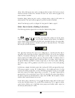
Enter Alarm Action Setting Sub-menu 

The following window appears after entering the Alarm Setting menu: 


Press 


ENT 

 to enter Alarm Action Setting menu. The first submenu is for fire alarm 

outputs. Use  


 and 


 to choose from different alarm menus for different 

events. Alarm output configuration for all events is basically the same. As an example, 

alarm output configuration for invalid card event is introduced below. The figure 

below shows the menu interface: 


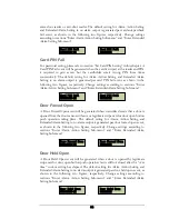
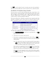
The upper line indicates the card to be configured, i.e., invalid card. The first 8 

characters of the lower line are alarm output status of this event on the door module, 

while the 2 characters following the minus sign are alarm output status on the Main 

alarm output and Auxiliary alarm output on the main module. Y indicates there is 

alarm output (relay energized) and N indicates there is no alarm output (relay not 

energized). R refers specifically to alarm output relay on the door module, indicating 

that alarm output will be generated only if the event occurs on the corresponding 

door. 

In the above example, the alarm output relay on door #1 will be energized if and only 

if the access request on door #1 is denied due to the invalid card event. On the 

contrary, the alarm output relay on door #8 will be energized as long as an invalid 

card event occurs. For alarm output relay on door #2~7, no alarm output will be 

generated due to the invalid card event. The NN following the minus sign indicates 

no alarm output from the Main alarm output and Auxiliary alarm output on main 

module when an invalid card event occurs. 

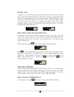
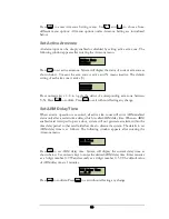
In this menu, press numeric key 1~8 to toggle the alarm output status of this event 

on the door module among Y, N, and R. Press numeric key 9,0 to toggle the alarm 

output status of this event on the Main alarm output and Auxiliary alarm output on 

the main module between Y and N. 

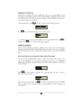
Alarm Action 
Setting 

Invalid Card 
RNNNNNNY-NN 

Содержание EFC-02-1A

Страница 1: ...User Manual F Fl le ex x S Se er ri ie es s C Co on nt tr ro ol ll le er r E EF FC C 0 02 2 1 1A A Volume 1 EverAccess...

Страница 2: ...2005 EverFocus Electronics Corp 1801 Highland Ave Duarte CA 91010 Phone 626 844 8888 Fax 626 844 8838 All rights reserved No part of the contents of this manual may be reproduced or transmitted in any...

Страница 3: ...ontroller 10 Reader Door Index Conversion 11 Terminal LED Definitions 11 Main Module Terminal Definition 11 Main Module LED Definition 12 Door Module Terminal Definition 13 Door Module LED Definition...

Страница 4: ...Connection to Backup Battery 30 Reset Controller 30 Cover Placement 31 Before First Use 31 CHAPTER 5 Controller Functionality and Configuration 33 General Operation Guideline 33 Enter System Configura...

Страница 5: ...cation 44 System Reader Setting 45 Door Setting 45 Enter Door Setting Menu 45 Open Time Setting 45 Set Door Hold Open Time 46 Set Door Behavior at Fire Alarm 46 Alarm Setting 47 Components for Alarm 4...

Страница 6: ...dress Setting 57 ARM DISARM 57 ARM The System using the Controller Keypad 57 Disarm the System using the Controller Keypad 58 Clear the Alarm 58 Arm Disarm the system using a reader 59 CHAPTER 6 Softw...

Страница 7: ...rm outputs on alarm module Maximum 18 alarm outputs with 4 installed door module and 1 alarm module Communication ports RS232 or RS485 Band rate 9600 Programmable duration Maximum 10 per day with mini...

Страница 8: ...ception which can be determined by turning the equipment off and on the user is encouraged to try to correct the interference by one of the following measures Reorient or relocate the receiving antenn...

Страница 9: ...can be connected via RS 485 bus or TCP IP networking requires additional LAN interface device Easy to use simple configuration operations can be performed at the controller using the integrated keypad...

Страница 10: ...manual 1 Flex Series software CD 1 software manual 2 supporting frames left and right 2 3mm 6mm screws to mount the controller to the frames Please Note If an item appears to have been damaged in shi...

Страница 11: ...le also controls the door and alarm modules 2 Terminals on main module Please refer to Ch 2 p 11 for the definitions and wiring directions 3 LCD screen The LCD screen displays the current status of th...

Страница 12: ...e LED on the door module shows the status of the door module Please refer to Ch 2 p 14 for more details 9 Alarm module The alarm module is used to extend the controller s alarm function adding up to 8...

Страница 13: ...nstallation Mount the controller and enclosure Install and connect the card readers Connect the electric strikes or mag locks Connect the controller to the system computer and desktop reader Mount a b...

Страница 14: ...by the access control system These access points will control the security of the facility and can limit the entry and exit to and from any given area of the building After deciding which doors need...

Страница 15: ...r each door This is important to consider when choosing the appropriate number of modules and readers Determining System Structure as well as the Number of Controller and Modules Determine how many co...

Страница 16: ...system and can be used to make changes to the database When choosing a location to mount the controller choose a clean dry location that will allow the administrator easy access to make changes to the...

Страница 17: ...e support frames Line up the four latches on the support frames with the holes on the controller base board Once lined up slide the controller base board down to secure it in place At this point the t...

Страница 18: ...m module can be installed to the controller Each door module is cascaded to its left side module till the main module The door modules and the alarm module can be placed in any sequence The index will...

Страница 19: ...ndex Conversion One EverAccess Flex Series controller can accommodate up to 4 door modules each of which controls 2 readers The index conversion of readers and is displayed below The readers doors are...

Страница 20: ...liary alarm output 15 Reserved 5 AUXAlarmOutCom Common pin of auxiliary alarm output 16 Reserved 6 AUXAlarmOutNC Normally close pin of auxiliary alarm output 17 Reserved 7 MainAlarmOutNo Normally open...

Страница 21: ...g card readers The right side terminals indexed from 1 16 control one reader while the left side terminals indexed from 17 32 are responsible for the 2nd reader as shown Fig 3 5 As described in the re...

Страница 22: ...l relay 2 12 Door1_COM Common pin for door control relay 1 28 Door2_COM Common pin for door control relay 2 13 Door1_NC Normally close pin for door control relay 1 29 Door2_NC Normally close pin for d...

Страница 23: ...mally open 8 Alarm1_COM Alarm 1 output in common 26 Alarm5_COM Alarm 5 output in common 9 Alarm1_NC Alarm 1 output for normally close 27 Alarm5_NC Alarm 5 output for normally close 10 Alarm2_ NO Alarm...

Страница 24: ...alarmed zone is in the alert delay stage Solid light on The alarm alert is on for the alarmed zone Light flashes quickly The alarmed zone is in danger alarm signal is input Install and Connecting the...

Страница 25: ...wo card readers Twisted cable is recommended to connect the controller and card readers The maximum transmission distance between the reader and controller depends on the gauge of the cable and the sp...

Страница 26: ...es an interface to two door control relays Terminals 11 13 are for door 1 connections and terminals 27 29 are for door 2 connections Terminals 12 and 28 are named common terminals COM Terminals 13 and...

Страница 27: ...es represents one lead of power from an external power source When using DC Voltage for the lock put the positive lead here When using AC the leads are interchangeable Connection to Door Sensor The in...

Страница 28: ...e four terminals terminal 9 and 25 are GND shared by the door sensor and request to exit 8 and 24 are your input signals Connection to Fire Alarm Input 0 The main module provides fire alarm input and...

Страница 29: ...terminals COM N O and N C The wiring depends on the alarm device Please read the user manual of the external alarm devices before wiring Using the 5th channel alarm signal output as an example the wir...

Страница 30: ...22 Fig 2 16 Normally Closed Connections for Alarm Output 5 N C COM N C terminal C terminal External Alarming Device 26 27 25 Alarm module...

Страница 31: ...ls should be wired to the computer serial port as follows the RS232 TX terminal of the controller is linked to the RS232 RX of the serial port and the RS232 RX terminal is linked to the TX If the cont...

Страница 32: ...the line 1 2 and 3 in RJ45 head as Fig 3 3 shows The RJ45 head is provided with the EverAccess desktop reader BA GND POWER CARD TX RX EverAccess 8 1 1 2 3 12 11 10 Fig 3 3 Connection to Desktop Reade...

Страница 33: ...X YZ CLR 0 EverAccess R X TX C A R D PO WER Figure 3 4 Connections of Multiple Controllers A brief overview of the installation 1 Connect the EverAccess desktop reader to the computer via USB port 2 C...

Страница 34: ...D E F AB C 2 1 4 5 6 9 8 7 SYS 0 CLR W XYZ T U V PQRS M N O JK L GH I 3 DE F A B C 2 1 4 5 6 9 8 7 SYS SYS 7 8 9 6 5 4 1 2 A B C DE F 3 G HI J K L M NO PQRS T UV WXYZ CLR 0 ENT ARM EverAccess EverAcce...

Страница 35: ...3 D E F AB C 2 1 4 5 6 9 8 7 SYS Serial 10Base T Reset 9 30 vdc ENT A RM EverAccess EverAccess S YS 7 8 9 6 5 4 1 2 A BC D EF 3 G H I J KL M N O P QRS T UV WX YZ CLR 0 Figure 3 9 Diagram for TCP IP ba...

Страница 36: ...in this guide Step 5 Connect the EA LAN1 to the controller Note Perform this step only after successfully completing steps 1 5 Step 6 Install the COM Port Simulator driver on the Admin PC using the C...

Страница 37: ...in the EverAccess enclosure is DC15V In addition the controller provides a 12V power supply for the card readers It should be noted that if a controller powers multiple card readers the current draw...

Страница 38: ...2 Connection to Backup Battery If a backup battery is connected the controller will automatically switch to backup power in the event that the external power is lost The backup battery will charge wh...

Страница 39: ...e latches are in place the bottom portion of the cover will fit easily over the rest of the controller base board Using the screws provided in the controller package secure the cover to the controller...

Страница 40: ...32 3 Configure reader properties 4 Configure alarm settings 5 Configure door setting 6 Configure the holidays and schedules...

Страница 41: ...above enters the system menu ARM arms or disarms the system The system menu is organized in a multiple level structure and toggle between the same level menu cancels or exits back to the higher level...

Страница 42: ...ion information of the currently installed firmware An example is shown below Display the Number of Installed Modules From the home screen press to show the number of installed door modules and alarm...

Страница 43: ...ting menu Use and to choose from different menu options All menu options in the System Setting Menu are introduced below Set Date Format User can choose between two date formats MM DD YYYY or YYY MM D...

Страница 44: ...ight Savings Time Under the System Setting Menu press ENT to adjust the settings for Auto Daylight Savings Press ENT to toggle the setting between Enabled Disabled Press to exit When auto daylight sav...

Страница 45: ...ime to confirm Press ENT to set the new system PIN Pressing at any time will exit the menu without changing the system PIN Set Arm PIN Arm PIN must be entered before the controller can be armed or dis...

Страница 46: ...The LCD will prompt the user to confirm the action Press ENT to confirm and perform the reset action Card Setting Card setting can be configured using either the controller or the EverAccess Flex Seri...

Страница 47: ...cquire the index number of the new card and add it to the controller Delete Cards The user can directly delete an individual card with a specific index or serial number from the controller or delete a...

Страница 48: ...al number as shown below After entering the serial number press ENT to enter the submenu for setting card properties Each card has 6 properties that can be modified Use and to choose desired propertie...

Страница 49: ...maximum of 32 time zone settings and defines access rights for all doors in the system Group setting is so complicated a process that it can only be performed using the EverAccess control software Use...

Страница 50: ...or If cardholder attempts to enter the same door again without first swipe the card to exit the door access is denied and the door will not open At the following submenu press ENT to enter Anti Passba...

Страница 51: ...will be displayed as shown below Press ENT to toggle between two statuses Press to exit Show Card Number This function can be used to show the serial number of a card when it is swiped on the system...

Страница 52: ...door modules In the following example 4 door modules 8 readers have been installed on the controller Press numeric keys to toggle the keypad setting of corresponding reader Press ENT to confirm Press...

Страница 53: ...to right According to card reader setting above users can allocate multiple readers to one single door User can directly set door open time door held open time and the door control at fire alarm on t...

Страница 54: ...alarm or not after the door sensor timeouts The default value of door hold open time is 5 seconds The maximal door hold open time supported by the controller is 999 minutes and 59 seconds At the follo...

Страница 55: ...le and one door module User can install three more door modules and one alarm module These three types of module are all equipped with alarm function The main module has 2 alarm inputs corresponding t...

Страница 56: ...her specify to which alarm output that event is allocated All events that might trigger an alarm are listed below Fire alarm zone alarm 1 8 unknown card expired card invalid card invalid door invalid...

Страница 57: ...acters following the minus sign are alarm output status on the Main alarm output and Auxiliary alarm output on the main module Y indicates there is alarm output relay energized and N indicates there i...

Страница 58: ...t is introduced below The figure below shows the menu interface The upper line indicates the card to be configured i e invalid card The first 8 characters of the lower line are alarm output status of...

Страница 59: ...es consecutively The default setting for Alarm Action Setting and Extended Alarm Setting is only Main alarm output on main module has alarm output per SYS PIN fail event as shown in the following two...

Страница 60: ...card that is never logged in the system An Unknown Card event will be generated when an unknown card is swiped on the reader The default setting for Alarm Action Setting and Extended Alarm Setting is...

Страница 61: ...ures respectively Change settings according to sections Enter Alarm Action Setting Sub menu and Enter Extended Alarm Setting Sub menu Invalid Time Each card belongs to an access group Each group has i...

Страница 62: ...nerated when controller detects that a door is opened from the door sensor without any legitimate swipe card or door open button push operation taking place The default setting for Alarm Action Settin...

Страница 63: ...the alarm time i e the time an alarm output remains active Under Alarm menu press twice to bring up the following window Press ENT to enter Alarm Time Setting submenu The current alarm time will be d...

Страница 64: ...ARM Delay Time When an arm operation is executed all active arm zones will enter ARM enabled status only after a certain time delay which is called ARM delay time When an ARM enabled card is swiped to...

Страница 65: ...8 alarm inputs EverAccess Flex Controller can treat alarm inputs in 8 arm zones in a very flexible manner These 8 arm zones can be armed or disarmed on the controller as described below Arm the Syste...

Страница 66: ...ssigned as the arm delay During this time no alarm outputs will be generated even if an alarm input is triggered Similar to the procedure to arm the system press ARM on the keypad Enter the ARM passwo...

Страница 67: ...dicates that the system is in arm delay period Flashing Quickly Indicates that the system is armed and some alarm input has triggered the alarm output The steps to arm or disarm the system at a keypad...

Страница 68: ...60 4 In any system mode press to exit the arm operation If no key is pressed for 20 seconds the reader will automatically log out of the arm operation mode...

Страница 69: ...the user accounts who will use the software 3 Configure the controller and all other hardware settings 4 Configure the holidays access group and the door control schedule 5 Enroll the cards and set th...

Страница 70: ...controller to the system Go to the controller configuration dialog box in the software Click the add button give the RS485 address for the controller set the serial port for the controller and click t...

Страница 71: ...s 2 Configure the access groups An access group defines a group of cardholders who share the same access rules at the associated access points and at specified times Set the access rules for the acces...

Страница 72: ...64 cardholders individually or can do batch configurations if a group of cardholders share common properties...

Страница 73: ...65 Notes...

Страница 74: ......

Страница 75: ...x 49 2822 939495 USA Office Beijing office 1801 Highland Ave Room 609 Technology Trade Building Duarte CA 91010 U S A Shangdi Information Industry Base Tel 1 626 844 8888 Haidian District Beijing Chin...

Отзывы: