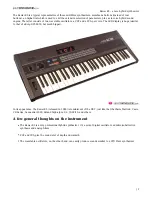
From EG to VCO
Also the EG can create a sort of auto-oscillation, in some way more stable and useful than the extreme
Emphasis settings just described (...but it can be mixed with...). With the
LOOP
mode set to ON and the
PERCUSSIVE
status selected, in some configurations it can reach around 170Hz in a quite limited waveform
variety, but still waveform... then you can route this oscillation, with it's level control and via the
VCF/VCA
switch, to the
MCƒ
(alias VCF) or the
STACCATO/CONTINUO
(alias
VCA
) controls and then see what happens. For
other details about the EG see the related section (
page 41)
Need an oscillator?
When you need an oscillator and nothing but Vertice is left in your lonely home after your divorce you
can obtain a very-hard tunable Oscillator simply patching the Rear A out into the Front A audio input. Try it
alone then, if you need some tip and tricks about this strange sort of analog oscillator, you can look at
page 54.
Need a disturbing Noise Generator?
You're too happy and feeling great in a brilliant shiny day with the sun up right there and smiling birds
flying around and suddenly need to return to your usual dark daily sadness? Vertice is here to help!
Why don't you bring out a 110dBrms pure electric satanic noise and let your hears spitting blood for all the
place? It's sounds a great idea! Try this:
Mode: Serial LP
Attitude: Diode
Emphasis: all three very high but not max
Cutoffs: try to match them.
There is a point, or a small range of, that the Diode Emphasis try to skip up your Cutoff. Here is the clue. If you set all the
three filterboards like that you have great chances to bring out one of the meanest brain-disturbing Noize Gen ever...
Not a VCO
The VERTICE is a filterbank, not an oscillator-bank. However it can oscillate, and quite loudly. The
auto-oscillation behaviors are very different besides the two attitude style. The Transistor mode has a more
"standard" way to oscillate, something you can find in the Ladder or other well known filters, only more
distorted and aggressive. The Diode way instead is not classic at all, and surely not predictable, at high
values. And, of course, in that extreme range of settings it does not follow any real V/oct parameter. Again,
our filterbank is not a precision tool, a bistoury. It’s more like a Viking battle-axe. We designed the alternative
resonance way (transistor) specifically to cover the lack of stability that high resonance value can give in the
passive Steiner's way. Then it comes out that distortion can be a welcomed plus and, after many circuits tried
and invented, the audio results of this choice is over your fingers. This Transistor way is to be intended like an
ALTERNATIVE and creative way to use our filterbank, not as "the standard", concept which Vertice does not
even understand. However if "a standard" is needed and mandatory to set a conceptual starting point, that
can be the Diode way at low settings.
[
26
]
the Filters section
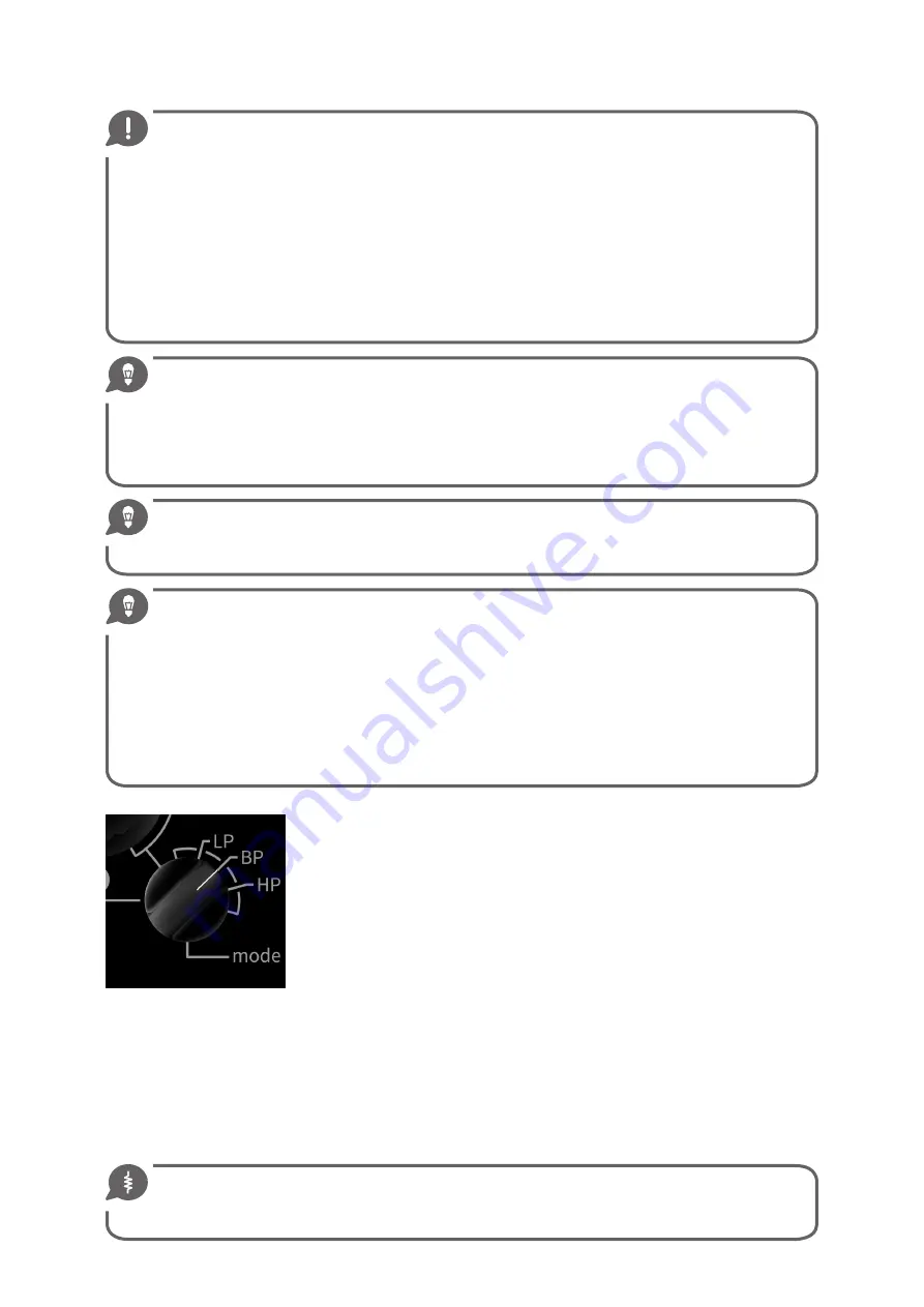
Mode varies the response of the singular filterboard between the three classic
states:
Low-pass, Band-pass, High-pass
. This control is independent for every one section.
Low-pass
means that the low frequency will be the last to disappear, cutted away
from the Cutoff action, in this case turning it counterclockwise.
High-pass
is the opposite of a Low-pass in both harmonic cutting and pot rotation ways.
Band-pass
is made serializing a Low-pass with a slighty more open Cutoff with
an High-pass with a relatively slightly lower Cutoff point, making them move
together, so only the central part of the harmonic content will pass through the
filter and see the rest of the world.
The basic and nominal slope in Vertice measure 12dB/oct, so quite tender. But it
can be less (10-11 dB/oct minimum when zero Emphasis is set. It depend also by the input signal level) or strongly
increased in various way using the Emphasis controls or the
PAR/SER
internal routing.
There follows some spectrum analysis (
Bode diagrams
) of the behavior of a single VERTICE filterboard. In this
case we investigate on the A filter with Steiner's classic resonance way (diode) inserted, changing the filtering
mode and reasoning a bit on what we see.
The
A-Cƒ
is set to
1kHz so the reference frequency for measurement is 2kHz, the octave up. The source is a
simple low frequency Moog sawtooth at medium level. The responses of the three filters are
highly dependent
on the input level.
-3dB
Note for those who do not use dB and Bode diagram everyday: a 3dB difference is a BIG difference. It
means in the most cases a gain (or loss) of the double (or half) of the perceived loudness. Please read the
following diagrams knowing it.
Содержание Vertice
Страница 1: ...USER S MANUAL...
Страница 2: ......
Страница 5: ...Dedicato a Walt Bruno e Lorenzina con immenso amore Stefano...
Страница 68: ...Ratio et Cogitatio Unicam Fidem Sunt...
Страница 69: ......
Страница 70: ......


