THE COMPONENTS
[
23
]
The audible results is a simple “neutral” flow of this low frequency signal.
If the input frequency is a very
high frequencies
signal instead, say 100kHz, the behavior will be opposite
than the previous one: the angular velocity
ω
is high and so Zc is near to zero making the first equation
become
V
out
=
0
Z
r
+
0
∙ V
input
=
0V
This means there is no signal flow to the output: it is all “discharged” to ground, the circuital equivalent of an
highway (less traffic = it is more easy to go fast. Charges always choose the faster way).
This considerations are true for the Low-pass configuration, but, read in “reversed mode”, are also true for
the High-pass modality.
So, this is the generic "engine" function behavior.
Now, if you are not dead yet, we can try to look inside the
frequency response
of a given-value system, putting
out circuit into three interesting situations.
The Cutoff frequency is located on the Hz line by resistor and capacitor sizing.
The relation here is
f
c
=
1
2
∙π ∙τ
=
1
2
∙π ∙ R ∙C
Using this formula you can know
where
the Cutoff frequency will be at given resistor-capacitor values. Now,
knowing the filters slope and mode you can easily deduce the behavior of the circuit, but you can't
explicate
it. You know what it does but you don't know
why
.
The equation to calculate F, the Frequency Response of the system, is
F
=
Z
c
Z
r
+
Z
c
Turning this equation into something useful is not exactly simple: this procedure involve Pythagoras and a vector
analysis of both Z and the phases involved, which capacitors systematically change as a construction characteristic.
This is not the right place to dwell around this argument, just be content of the sequent little reasoning.
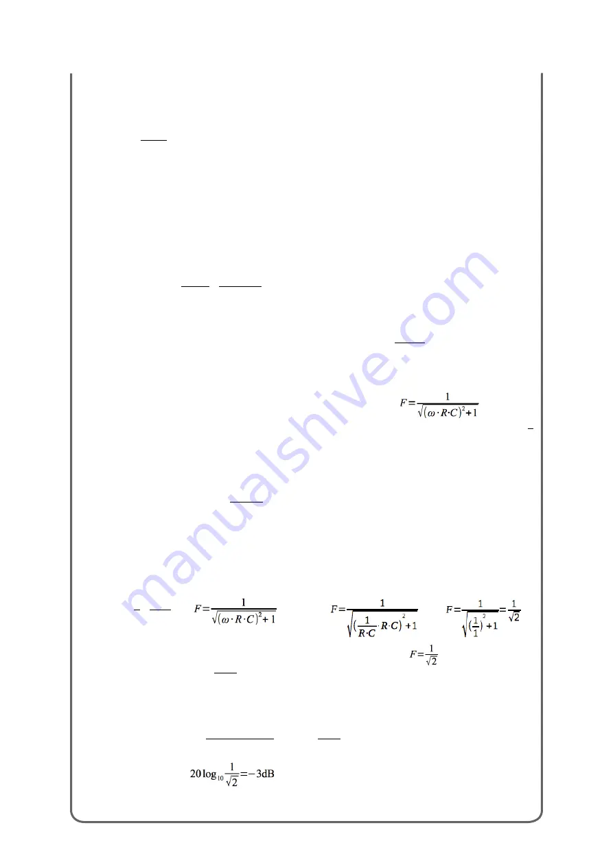
Using Pythagoras and vectors we can transform the previous equation into
When we are in the
low frequency range, injecting a low frequency signal,
ω
is equal to zero, so
F
=
1
1
meaning the gain of the whole structure equal to 1, so “transparent”. All the injected spectrum have the same
gain factor. No attenuations on this low freq signal by this circuit.
When we are in the
high frequency range, injecting an high frequency signal,
ω
is comparable with ∞ so the
previous equation will become
F
=
1
ω∙ R∙C
(we can 1 because of the high value of
ω
). In this range
you can observe a
progressive
gain decrease when you increase the input frequency. A classic low-pass
behavior. The progressive characteristic is due to the
transient
comportment of the universe: in this case the
greater the frequency the smaller the gain.
When we are in the
Cutoff frequency range, inputting an audio waveform with frequency value
comparable
to the position of the Cutoff frequency of the circuit we are in a
particular situation:
by definition
τ
=
R ∙C
If
ω
=
ω
cutoff
=
1
τ
=
1
R ∙C
so
become so
The two
R·C
modules are erased by themselves so the final equation become
which is another way to say
F
=
V
out
V
input
Now, since this formula can't be so exhaustive as it is we are forced to turn it into a more recognizable form.
To derive dB values from a measure you can use the Pressure Level dB general equation.
It can be expressed as
20log
10
measured value
reference value
=
20log
10
V
out
V
input
so we can conclude that:
This is why all the filters across the world shows a -3dB behavior on the Cutoff frequency.
Содержание Vertice
Страница 1: ...USER S MANUAL...
Страница 2: ......
Страница 5: ...Dedicato a Walt Bruno e Lorenzina con immenso amore Stefano...
Страница 68: ...Ratio et Cogitatio Unicam Fidem Sunt...
Страница 69: ......
Страница 70: ......


