


4 - 6
4
590SP Digital Product Manual
Chapter 4 Start-up and Adjustment
DIGTIAL
5. If the motor continues to run away after checking the feedback sign and field polarity check whether the
drive actually receives it speed feedback signal. Monitor DIAGNOSTICS:: TACH VOLTS when using
an analog tachometer generator. For Microtach or wire-ended encoders, check DIAGNOSTICS::
ENCODER RPM. Verify the connections and supply wiring to the feedback device if it fails to generate
a feedback signal. If the drive trips on either SPEED FEEDBACK alarm or ENCODER FAILED alarm,
verify that the SPDFBK ALARM LEVEL, ENCODER RPM and ENCODER LINES parameters are
properly set.
6. If the motor does not turn at all, increase the CURRENT LIMIT to 50% or greater and monitor DIAG-
NOSTIC:: CURRENT FEEDBACK. If CURRENT FEEDBACK still reads 0.00%, turn the power off
and check the armature connections. If the problem persists, refer to Chapter 7 for detailed trouble-
shooting information.
7. If the drive is regenerative and the application requires reverse rotation, provide a negative speed
demand, start the drive and verify that the motor runs in the reverse direction.
8. After you have correctly set the direction of rotation, reset CURRENT LIMIT to the desired value. If in
doubt, set CURRENT LIMIT to 110% to correspond to 110 % full load current. If CURRENT LIMIT is set
to a maximum 200%, and the motor runs into an overload condition, the current limit automatically reduces
on an inverse time curve from the overload level down to 110% full load current.
NOTE. The motor may overheat if it continues to rotate while at current limit. Thermal
protection should be provided. If the motor is overloaded and there is insufficient controller
current to maintain rotation, the motor will stall, and the controller will trip out on the STALL
TRIP alarm if this alarm is enabled.
9. Stop the drive then SAVE PARAMETERS.
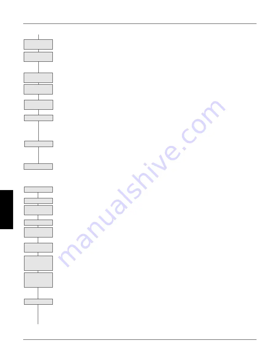
Check Reversing
if Applicable
Reset I Limit
Stall Trip
SPEED FEEDBACK CALIBRATION
Save Parameters
No feedback
signal?
Check
Connections
Motor Does not
turn?
Increase I Limit to
50%
▼
Start the drive, gradually increase the speed demand signal to 50% and monitor DIAGNOSTICS:: TERMI-
NAL VOLTS, which is displayed in percentages. Measure the actual armature voltage on the drive output
with a DC voltmeter. TERMINAL VOLTS should read within 10% of the actual value. For example, when
measuring armature volts at terminals A+ and A- with a digital volt meter, a 180 volt armature should read
90 volts at 50% speed demand, and the MMI should display 50% under TERMINAL VOLTS. If the
reading is outside this range, check the drive's voltage calibration switches before continuing.
Increase the speed demand to maximum and check the shaft speed accuracy with a hand tachometer.
Measure the armature voltage. If fine adjustment is needed, adjust the drive's calibration as appropriate to
the speed feedback selection.
1. ARMATURE VOLTAGE FEEDBACK
Armature voltage feedback uses the motor's back EMF as speed feedback and is the drive's default
feedback setting. It requires no feedback device, isolator or additional external connections. The scaling
parameter, SETUP PARAMETERS:: CALIBRATION:: ARMATURE V CAL, fine tunes the drive's
armature voltage calibration and has a range of 1.1000 to 0.9800, corresponding to -10% to +2% trim.
Changes outside this range require re-calibration of the motor voltage switch settings (switches S1
through S4) as described in Chapter 3.
IR COMPENSATION SETUP
Properly setting the IR COMPENSATION parameter, or motor loss compensation, improves the speed
accuracy when running in armature voltage feedback.
•
Run the motor without a load. Monitor the actual speed with a hand tachometer.
•
With the same speed setpoint, run the motor at full load and monitor the actual speed again with a
hand tachometer.
•
Adjust IR COMPENSATION until the full load speed is the same as the no load speed.
NOTE. Too much IR COMPENSATION causes instability.
Start Drive
Run at half speed
Run at full speed
Monitor speed
with hand tach
Armature Voltage
Feedback
Fine tune: Set
ARMATURE V
CAL
Coarse scale: Set
Voltage Switches
S1-S4
Monitor Armature
Volts
IR Compensation
▼
Содержание 590SP
Страница 2: ......
Страница 16: ...1 4 590SP Digital Product Manual 1 Chapter 1 Introduction ...
Страница 18: ...2 2 2 590SP Digital Product Manual Chapter 2 Identification ...
Страница 31: ...Figure 3 3 Wiring Circuit Diagram for 590SP Digital Drive ...
Страница 41: ...4 10 4 590SP Digital Product Manual Chapter 4 Start up and Adjustment DIGTIAL ...
Страница 66: ...6 590SP Digital Product Manual Chapter 6 Service and Maintenance 6 5 Figure 6 4 Replacing the SCR Packs ...
Страница 67: ...6 590SP Digital Product Manual Chapter 6 Service and Maintenance 6 6 ...
Страница 88: ...B Appendix B Using the Man Machine Interface App B 3 590SP Digitial Product Manual Figure B 1 Basic Menu Tree ...
Страница 89: ...B Appendix B Using the Man Machine Interface App B 4 590SP Digitial Product Manual ...
Страница 96: ...Appendix C Setup Parameters 590 DRV Digital DC Drive Product Manual App C 7 C Figure C 8 Aux I O ...
Страница 102: ...Appendix C Setup Parameters 590 DRV Digital DC Drive Product Manual App C 13 C Figure C 16 Current Profile ...
Страница 104: ...Appendix C Setup Parameters 590 DRV Digital DC Drive Product Manual App C 15 C t t t Figure C 17 Stop Rates ...
Страница 110: ...Appendix C Setup Parameters 590 DRV Digital DC Drive Product Manual App C 21 C Figure C 22 Setpoint Sum ...
Страница 114: ...Appendix C Setup Parameters 590 DRV Digital DC Drive Product Manual App C 25 C Figure C 25 Speed Loop ...
Страница 118: ...Appendix C Setup Parameters 590 DRV Digital DC Drive Product Manual App C 29 C Figure C 27 Speed Loop Setpoints ...
Страница 120: ...Appendix C Setup Parameters 590 DRV Digital DC Drive Product Manual App C 31 C Figure C 28 Current Loop ...
Страница 122: ...Appendix C Setup Parameters 590 DRV Digital DC Drive Product Manual App C 33 C Figure C 29 Inhibit Alarms ...
Страница 124: ...Appendix C Setup Parameters 590 DRV Digital DC Drive Product Manual App C 35 C Figure C 30 Calibration t ...
Страница 125: ...Appendix C Setup Parameters 590 DRV Digital DC Drive Product Manual App C 36 C ...
Страница 145: ...Appendix D I O Configuration System Menu App D 20 D 590SP Digital DC Drive Product Manual Figure D 17 Block Diagram ...
Страница 149: ...Appendix D I O Configuration System Menu App D 24 D 590SP Digital DC Drive Product Manual ...
Страница 150: ...t t t t Figure D 20 590SP Digital Software Block Diagram ...
Страница 160: ...590SP Digital Product Manual App E 10 E Appendix E MMI Parameter List ...
Страница 168: ...Appendix G RS232 System Port P3 590SP Digital Product Manual App G 6 G ...
Страница 173: ...590SP Digital Product Manual App H 5 Appendix H RS422 Communications Ports P1 P2 H Figure H 3 PNO Config Block Diagram ...
Страница 194: ...Appendix H RS422 Communications Ports P1 P2 590SP Digital Product Manual App H 26 H ...
Страница 218: ...App L 4 590SP Digital Product Manual L Appendix L 590SP DRV Option Figure L 3 590SP Digital DRV Layout Diagram ...
Страница 219: ...590SP Digital Product Manual App L 5 L Appendix L 590SP DRV Option Figure L 4 590SP Digital DRV Schematic Diagram ...
Страница 220: ...App L 6 590SP Digital Product Manual L Appendix L 590SP DRV Option ...
Страница 221: ...Figure L 5 Wiring Circuit Diagram for 590SP Digital DRV Drive ...
Страница 224: ...590SP Digital Product Manual App M 3 Appendix M Special Blocks and Application Notes M Figure M 1 Diameter Calculator ...
Страница 228: ...590SP Digital Product Manual App M 7 Appendix M Special Blocks and Application Notes M Figure M 5 Setpoint Sum 2 ...
Страница 259: ...590SP Digital Product Manual App M 38 Appendix M Special Blocks and Application Notes M ...


