


Chapter 3 Installation and Wiring
590SP Digital Product Manual
3 - 4
3
▼
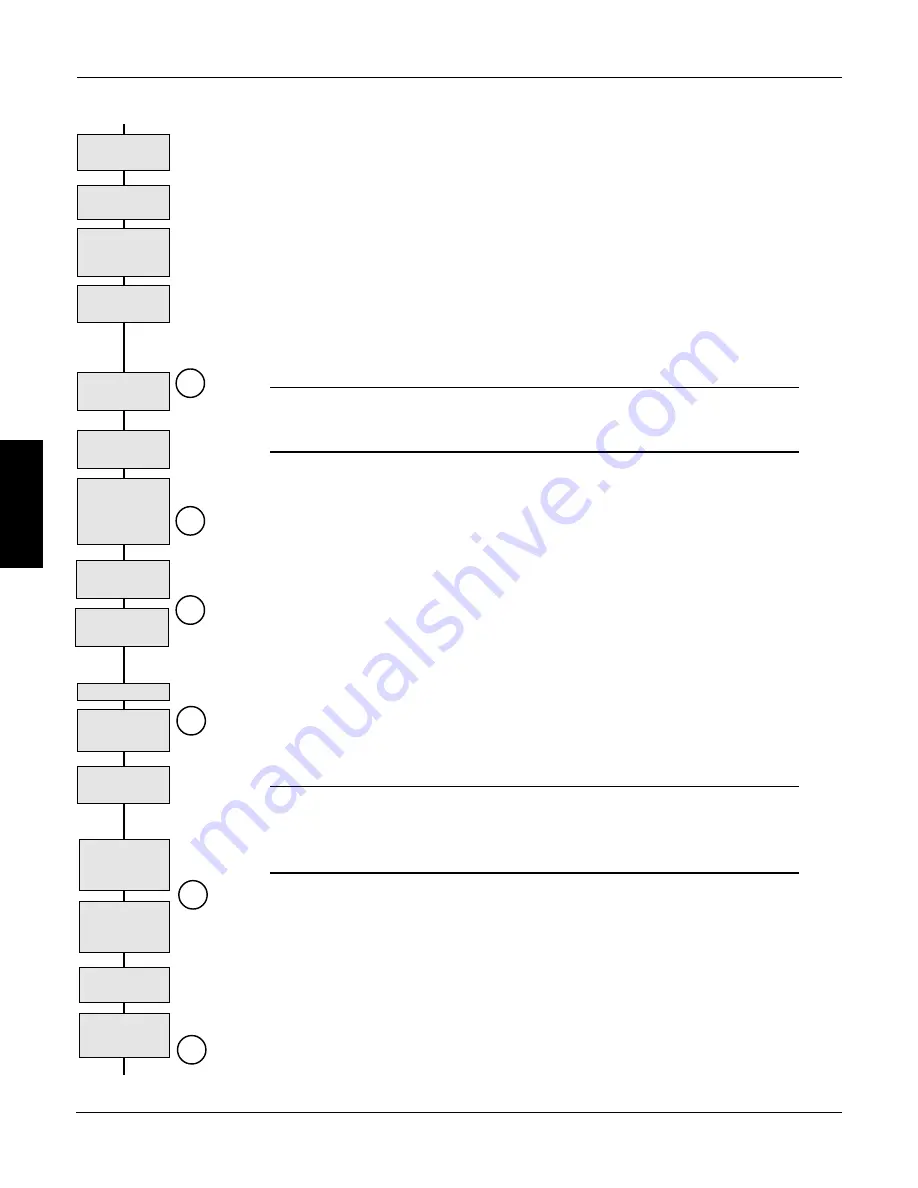
AC Conductor
Ratings
Main Supply
Connections
DC Conductor
Ratings
Control, Field &
Signal Wire
Ratings
Supply Ground
Connection
3-wire Supply
only
Use AC Branch
Circuit Protection,
SCR fuses
optional
Connect Field
▼
Check Jumpers
JP1 and JP2
External Field
Supply?
C
1/2 - Wave
Rectifier Wiring
(see note 6)
Wire Ampacity and Supply Rating
The input supply conductors must be rated for 1.25 x AC input current. The AC input current is ap-
proximately 1.5 x full load motor current. The DC armature output conductors must have a mini-
mum rating of 1.1 x full load motor current. UL requires the armature conductors to be rated for 1.25
x full load motor current. Refer to the acceptable wire sizes for the terminals listed in Figure 3.4.
The motor field wiring should be at least 14 AWG. Signal wiring (conductors to terminal block A)
and control power wiring must be 18 gauge or larger. The ground connection for the 590SP is at the
bottom left corner of the heatsink (refer to Figure 3.5). The ground connection requires 10 AWG (4
mm
2
) wire minimum, terminated with a ring lug crimp.
Main Supply and Armature Connections
Connect the AC power supply to terminals L1 and L2, and power input ground to the ground screw. The
connections must be made through adequate branch AC circuit protection, as per applicable code.
Caution
The 590SP is designed to accept a grounded supply. Supplying the drive from a two-
wire, non-grounded supply is not recommended.
NOTE. Only branch AC circuit protection for the drive is required. Semiconductor
fuses are optional. If you wish to use semiconductor fuses for the drive's thyristors,
size the fuses according to the I
2
t rating of the thyristor. These ratings are listed in
Appendix A, Technical Details.
The armature output and supply input connections are located at the bottom of the power board, as
shown in Figure 3.5. If using an AC contactor, connect the motor armature directly to terminals A+
and A–. If using a DC contactor, wire the contactor's normally open poles between these terminals
and motor armature (see Figure 3.3). Connect the motor ground wire to the AC supply ground
connection at the bottom left corner of the heat sink. Use 10 AWG (4 mm
2
) minimum wire and
terminate with a spade crimp.
Field Supply Connections
Connect the motor field (-) to terminal D3 and field (+) to terminal D4. When an external field is
required (for example, when a 240 VDC field is required on a 240 VDC armature motor), connect
the supply wires to terminals D1 and D2. Switch auxiliary control jumpers JP1 and JP2 from
positions 2 and 3 to positions 1 and 2. These jumpers are on the lower left of the power board as
shown in Figure 3.5 and number from left to right as shown in Figure 3.6.
WARNING!
The drive's on board field rectifier is completely non-controlled. Shutting off supply
power or disabling the drive may not switch off the field supply. Check the field
voltage after removing power and before servicing the drive.
If connecting the rectifier for half-wave rectification, be certain to wire the field as described in Note 6 of
Figure 3.3.
If the motor has a permanent magnet field, or if you are powering the field from a separate source, leave
terminals D3 and D4 unconnected and move the field control jumpers JP1 and JP2 from positions 2
and 3 to positions 1 and 2.
Control Power Wiring
The drive is shipped with the control power supplied by the main drive supply and accepts a voltage
range of 110 to 240 VAC without changing the tapping. For main supplies exceeding 240 VAC,
however, the control supply must be supplied externally through terminals D7 (neutral) and D8
Check Control
Power Rating
External Control
Supply?
PM Motor? Move
JP1 & JP2 to
positions 1 & 2
D
F
B
A
Armature
Connections
Motor Ground
Connection
E
Содержание 590SP
Страница 2: ......
Страница 16: ...1 4 590SP Digital Product Manual 1 Chapter 1 Introduction ...
Страница 18: ...2 2 2 590SP Digital Product Manual Chapter 2 Identification ...
Страница 31: ...Figure 3 3 Wiring Circuit Diagram for 590SP Digital Drive ...
Страница 41: ...4 10 4 590SP Digital Product Manual Chapter 4 Start up and Adjustment DIGTIAL ...
Страница 66: ...6 590SP Digital Product Manual Chapter 6 Service and Maintenance 6 5 Figure 6 4 Replacing the SCR Packs ...
Страница 67: ...6 590SP Digital Product Manual Chapter 6 Service and Maintenance 6 6 ...
Страница 88: ...B Appendix B Using the Man Machine Interface App B 3 590SP Digitial Product Manual Figure B 1 Basic Menu Tree ...
Страница 89: ...B Appendix B Using the Man Machine Interface App B 4 590SP Digitial Product Manual ...
Страница 96: ...Appendix C Setup Parameters 590 DRV Digital DC Drive Product Manual App C 7 C Figure C 8 Aux I O ...
Страница 102: ...Appendix C Setup Parameters 590 DRV Digital DC Drive Product Manual App C 13 C Figure C 16 Current Profile ...
Страница 104: ...Appendix C Setup Parameters 590 DRV Digital DC Drive Product Manual App C 15 C t t t Figure C 17 Stop Rates ...
Страница 110: ...Appendix C Setup Parameters 590 DRV Digital DC Drive Product Manual App C 21 C Figure C 22 Setpoint Sum ...
Страница 114: ...Appendix C Setup Parameters 590 DRV Digital DC Drive Product Manual App C 25 C Figure C 25 Speed Loop ...
Страница 118: ...Appendix C Setup Parameters 590 DRV Digital DC Drive Product Manual App C 29 C Figure C 27 Speed Loop Setpoints ...
Страница 120: ...Appendix C Setup Parameters 590 DRV Digital DC Drive Product Manual App C 31 C Figure C 28 Current Loop ...
Страница 122: ...Appendix C Setup Parameters 590 DRV Digital DC Drive Product Manual App C 33 C Figure C 29 Inhibit Alarms ...
Страница 124: ...Appendix C Setup Parameters 590 DRV Digital DC Drive Product Manual App C 35 C Figure C 30 Calibration t ...
Страница 125: ...Appendix C Setup Parameters 590 DRV Digital DC Drive Product Manual App C 36 C ...
Страница 145: ...Appendix D I O Configuration System Menu App D 20 D 590SP Digital DC Drive Product Manual Figure D 17 Block Diagram ...
Страница 149: ...Appendix D I O Configuration System Menu App D 24 D 590SP Digital DC Drive Product Manual ...
Страница 150: ...t t t t Figure D 20 590SP Digital Software Block Diagram ...
Страница 160: ...590SP Digital Product Manual App E 10 E Appendix E MMI Parameter List ...
Страница 168: ...Appendix G RS232 System Port P3 590SP Digital Product Manual App G 6 G ...
Страница 173: ...590SP Digital Product Manual App H 5 Appendix H RS422 Communications Ports P1 P2 H Figure H 3 PNO Config Block Diagram ...
Страница 194: ...Appendix H RS422 Communications Ports P1 P2 590SP Digital Product Manual App H 26 H ...
Страница 218: ...App L 4 590SP Digital Product Manual L Appendix L 590SP DRV Option Figure L 3 590SP Digital DRV Layout Diagram ...
Страница 219: ...590SP Digital Product Manual App L 5 L Appendix L 590SP DRV Option Figure L 4 590SP Digital DRV Schematic Diagram ...
Страница 220: ...App L 6 590SP Digital Product Manual L Appendix L 590SP DRV Option ...
Страница 221: ...Figure L 5 Wiring Circuit Diagram for 590SP Digital DRV Drive ...
Страница 224: ...590SP Digital Product Manual App M 3 Appendix M Special Blocks and Application Notes M Figure M 1 Diameter Calculator ...
Страница 228: ...590SP Digital Product Manual App M 7 Appendix M Special Blocks and Application Notes M Figure M 5 Setpoint Sum 2 ...
Страница 259: ...590SP Digital Product Manual App M 38 Appendix M Special Blocks and Application Notes M ...


