


590SP Digital Product Manual
App. M - 32
Appendix M Special Blocks and Application Notes
M
Startup Procedures for Tension or Dancer Position Control
The following procedures describe a methodology for starting and tuning a tension control line drive section. The first
steps assure the drive section parts are calibrated correctly. The PID setup steps tune the section for best performance.
Initial Section Setup
1. Set all the PID parameters to the default values (see Appendix H).
2. Disable PID:: ENABLE at terminal C7.
3. Verify SETPOINT SUM 1:: RATIO 0 is set to 100.00 percent and set terminal A2, DRAW/
RATIO, to 0 volts.
4. Calibrate the feedback device.
a. When using loadcell feedback, see the manufacturer's manual for calibration instructions.
b. When using dancer feedback, verify that the dancer polarity is correct and the dancer posi-
tion setpoint is for mid-position.
5. Start up the drive as described in Chapter 4 (that is, AUTOTUNE the current loop, etc.).
6. Match the roll surface speed of the line drive section to the master drive surface speed using the
590 encoder or tachometer calibration as appropriate.
At this point, the loadcell or dancer, drive, and drive sections should be functioning properly.
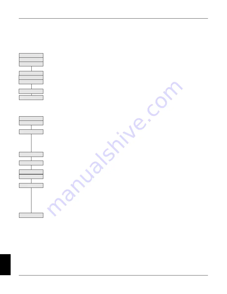
PID Adjustment
Check PID settings
Disable PID
Disable Draw
Calibrate feedback
Loadcell
Dancer
Ch 4 Startup
Match surf speed
Int. Defeat ON
Set O/P Scaler
Check Prop. Gain
Loadcell
Dancer
Int. Defeat OFF
Integral action
Derivative
1. Set INT. DEFEAT to ON to provide proportional control only.
2. Set O/P SCALER (TRIM) to suit the type of web. As a rough guide, use 2 to 5 percent for a
non-extensible web and 5 to 10 percent for an extensible web.
3. With a web in the machine, run the line at a low speed with the PID enabled, terminal C7.
Check the tension loop performance by making step changes in tension and monitoring the
feedback. Increasing PROP. GAIN gives faster response but at some point the section will be-
come unstable. When the section becomes unstable, reduce PROP. GAIN a little until it regains
stability.
a. For loadcell feedback, check the performance by making step changes in the tension de-
mand and monitoring the tension feedback.
b. For dancer feedback, check the performance by manually moving the dancer and watching
it return to the center position.
4. After achieving stable proportional control, set INT. DEFEAT to OFF.
5. The integral action ensures a zero steady state error at all line speeds. Reduce INT. TIME
CONST. to improve response; however, if the time is set too short, instability will occur.
6. Derivative gain can improve stability, particularly where the PID has a wide control range, or
for tension systems using high inertia dancer rolls. If the position loop repsonse is overdamped,
increase DERIVATIVE TC slowly until the reponse is critically damping.
NOTE. PID tension controlled system are highly sensitive to changes in derivative gain.
Make changes in the the DERIVATIVE TC in small increments only.
In most cases, derivative gain introduces oscillations and system instability and therefore
should not be used. Loadcell feedback systems usually do not require derivative gain. For
loadcell control, leave DERIVATIVE TC set to zero.
7. PID OUTPUT can be monitored in the DIAGNOSTICS menu of the MMI. This can be very use-
ful when diagnosing problems. If the speed tracking is incorrect, PID OUTPUT will rise because
the PID must provide an increasing trim as speed rises. If the web is slipping at the tension
control section, PID OUTPUT will saturate at 100 percent since the trim cannot produce ten-
sion. If the trim polarity is incorrect, PID OUTPUT will saturate and the web will be either too tight
or too loose.
Other Settings
Trim Range
O/P SCALER (TRIM) scales the PID output to produce the speed trim. It sets the amount of overspeed the PID trim
produces and the polarity of the trim. The polarity should be positive when the feedback devices are upstream of the
drive and negative when downstream of the drive.
Check PID Output
Содержание 590SP
Страница 2: ......
Страница 16: ...1 4 590SP Digital Product Manual 1 Chapter 1 Introduction ...
Страница 18: ...2 2 2 590SP Digital Product Manual Chapter 2 Identification ...
Страница 31: ...Figure 3 3 Wiring Circuit Diagram for 590SP Digital Drive ...
Страница 41: ...4 10 4 590SP Digital Product Manual Chapter 4 Start up and Adjustment DIGTIAL ...
Страница 66: ...6 590SP Digital Product Manual Chapter 6 Service and Maintenance 6 5 Figure 6 4 Replacing the SCR Packs ...
Страница 67: ...6 590SP Digital Product Manual Chapter 6 Service and Maintenance 6 6 ...
Страница 88: ...B Appendix B Using the Man Machine Interface App B 3 590SP Digitial Product Manual Figure B 1 Basic Menu Tree ...
Страница 89: ...B Appendix B Using the Man Machine Interface App B 4 590SP Digitial Product Manual ...
Страница 96: ...Appendix C Setup Parameters 590 DRV Digital DC Drive Product Manual App C 7 C Figure C 8 Aux I O ...
Страница 102: ...Appendix C Setup Parameters 590 DRV Digital DC Drive Product Manual App C 13 C Figure C 16 Current Profile ...
Страница 104: ...Appendix C Setup Parameters 590 DRV Digital DC Drive Product Manual App C 15 C t t t Figure C 17 Stop Rates ...
Страница 110: ...Appendix C Setup Parameters 590 DRV Digital DC Drive Product Manual App C 21 C Figure C 22 Setpoint Sum ...
Страница 114: ...Appendix C Setup Parameters 590 DRV Digital DC Drive Product Manual App C 25 C Figure C 25 Speed Loop ...
Страница 118: ...Appendix C Setup Parameters 590 DRV Digital DC Drive Product Manual App C 29 C Figure C 27 Speed Loop Setpoints ...
Страница 120: ...Appendix C Setup Parameters 590 DRV Digital DC Drive Product Manual App C 31 C Figure C 28 Current Loop ...
Страница 122: ...Appendix C Setup Parameters 590 DRV Digital DC Drive Product Manual App C 33 C Figure C 29 Inhibit Alarms ...
Страница 124: ...Appendix C Setup Parameters 590 DRV Digital DC Drive Product Manual App C 35 C Figure C 30 Calibration t ...
Страница 125: ...Appendix C Setup Parameters 590 DRV Digital DC Drive Product Manual App C 36 C ...
Страница 145: ...Appendix D I O Configuration System Menu App D 20 D 590SP Digital DC Drive Product Manual Figure D 17 Block Diagram ...
Страница 149: ...Appendix D I O Configuration System Menu App D 24 D 590SP Digital DC Drive Product Manual ...
Страница 150: ...t t t t Figure D 20 590SP Digital Software Block Diagram ...
Страница 160: ...590SP Digital Product Manual App E 10 E Appendix E MMI Parameter List ...
Страница 168: ...Appendix G RS232 System Port P3 590SP Digital Product Manual App G 6 G ...
Страница 173: ...590SP Digital Product Manual App H 5 Appendix H RS422 Communications Ports P1 P2 H Figure H 3 PNO Config Block Diagram ...
Страница 194: ...Appendix H RS422 Communications Ports P1 P2 590SP Digital Product Manual App H 26 H ...
Страница 218: ...App L 4 590SP Digital Product Manual L Appendix L 590SP DRV Option Figure L 3 590SP Digital DRV Layout Diagram ...
Страница 219: ...590SP Digital Product Manual App L 5 L Appendix L 590SP DRV Option Figure L 4 590SP Digital DRV Schematic Diagram ...
Страница 220: ...App L 6 590SP Digital Product Manual L Appendix L 590SP DRV Option ...
Страница 221: ...Figure L 5 Wiring Circuit Diagram for 590SP Digital DRV Drive ...
Страница 224: ...590SP Digital Product Manual App M 3 Appendix M Special Blocks and Application Notes M Figure M 1 Diameter Calculator ...
Страница 228: ...590SP Digital Product Manual App M 7 Appendix M Special Blocks and Application Notes M Figure M 5 Setpoint Sum 2 ...
Страница 259: ...590SP Digital Product Manual App M 38 Appendix M Special Blocks and Application Notes M ...


