Issue 2, Nov-98. Applies to software versions 1.3 & 1.4 -9- HA026270
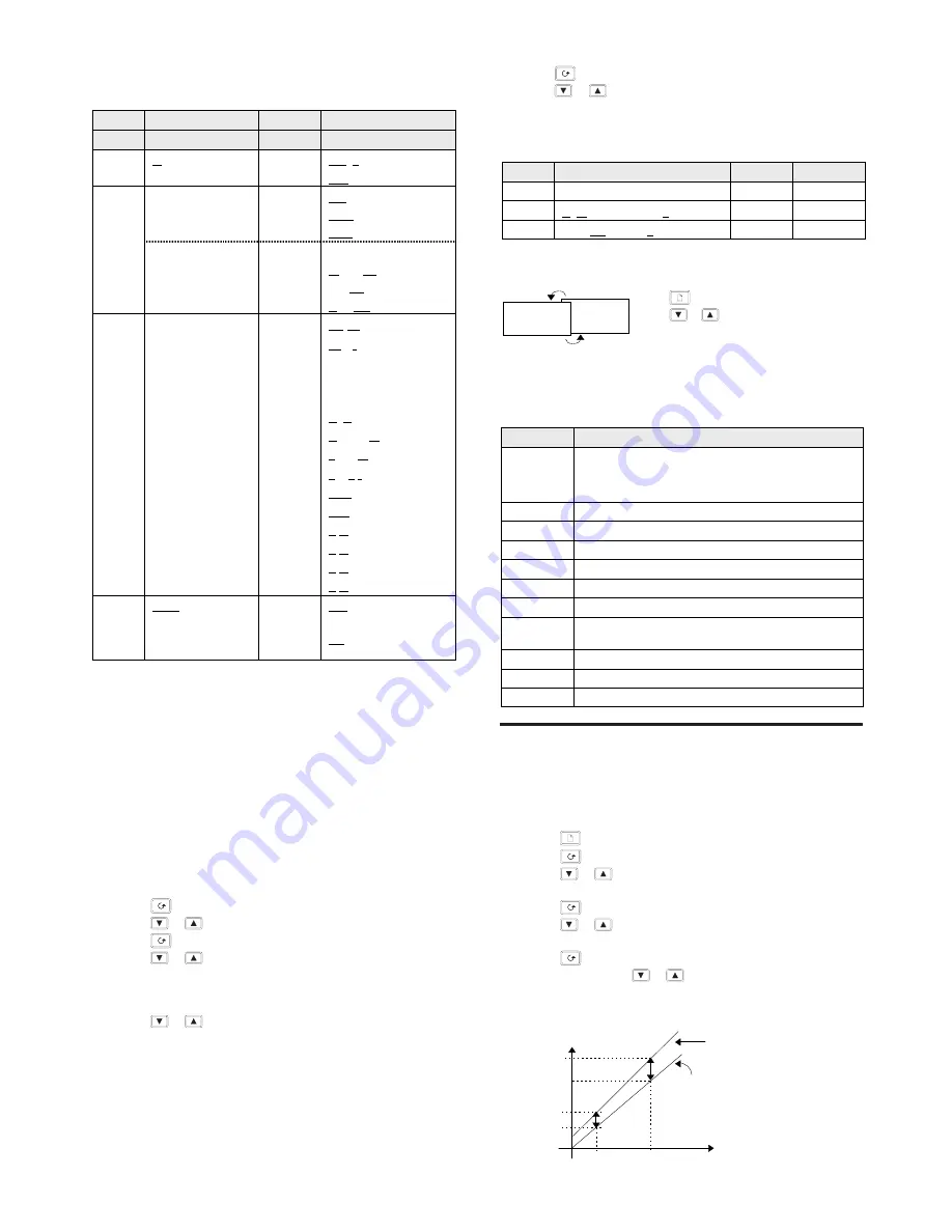
Relay and Logic input/output Configuration
Note: The logic I/O can be configured as an output or a contact
closure input for alarm acknowledge, keylock, or timer run/reset.
Relay output
Options
Meaning
Logic I/O
Identity of output
-
Relay
.
Logic
Function
.
Digital (alarm) output
Heating output
Cooling output
These functions
'
PDSIO mode 1
are only appear
Alarm Acknowledge
Keylock digital input
for the logic I/O
(
Run/reset timer
.
Digital output
)
No change
functions
Clear all alarms
'
Alarm 1
(See note 1)
Alarm 2
(See note 1)
See below: “ To
+
Alarm 3
(See note 1)
Operate the relay
*
New alarm
or logic output
*
Sensor break alarm
from an alarm or
*
Loop break alarm
digital function”
*
Load fail alarm
*
Man mode active
*
End of timing
.'
*
Timer running
.
*
Timer counting down
(See note 2)
.+
*
Timer running
(See note 2)
.#
*
Timer counting down
Sense of the
output
Normal (heating or
cooling outputs)
%
Inverted (for alarms
de-energises in alarm)
* These alarms are always non-latching. Process alarms 1, 2 and 3
are configurable as alarm latching or non-latching, see the ‘
’ List
Note 1: The last three letters will correspond to the alarm type
configured in the
list. If the alarm is disabled, or
or
will be shown.
Note 2:
and
are special functions. If selected, they
illuminate the logic or relay output beacons, OP1 and OP2, without
operating the actual output. They are used to indicate that timing is
in progress while leaving the actual outputs to be operated by the
other digital functions such as the END condition which can be
used to operate an external klaxen.
To Operate the Relay or Logic output from an alarm or
digital function.
1. Press until you reach
2. Press
or
to select
=
3. Press to reach
4. Press
or
to select a alarm or digital function
5.
Leave for 2 seconds. The display returns to
and
connects the selected alarm or digital function to the relay or
logic output.
6. Press
or
again. Two decimal points will appear in the
function that has been added to the output.
Multiple Alarms on one Output
Any number of alarms or digital functions can be added to the
relay or logic output by repeating steps 4, 5 and 6 above. Two
decimal points will appear in those functions that has been added
to the output.
........Continued in the next column
To Clear Alarms from an Output
1. Press
until to reach
2. Press
or
to select
!
3. Leave for 2 seconds. The display returns to
which
disconnects all alarms from the relay.
Passwords
Passwords
Range
Default
Full and Edit level password
/0000
Configuration level password
/0000
User calibration password
/0000
To leave Configuration level
Diagnostic Alarms
In addition to the normal process alarms, the following diagnostics
alarm messages are provided.
Message
Meaning and (Action)
Electrically Erasable Memory Error:
A parameter value has been corrupted.
Contact Eurotherm Controls.
1
Hardware error: ( Return for repair)
Low display range exceeded: (Check input signal)
High display range exceeded: (Check input signal)
'
Error 1: ROM self-test fail. (Return for repair)
Error 2: RAM self-test fail. (Return for repair)
+
Error 3: Watchdog fail. (Return for repair)
#
Error 4: Keyboard failure. Stuck button, or a button
was pressed during power up.
$
Error 5: Input circuit failure. (Return for repair)
Power failure. The line voltage is too low.
23
Tune Error. Appears if auto-tuning exceeds 2 hours.
U
SER CALIBRATION
Your controller has been calibrated for life against known
reference sources. User calibration allows you to apply offsets to
compensate for sensor and other system errors. The parameter
in the list applies a fixed offset over the whole display
range. You may also apply a 2-point calibration as follows:
•
Press
until you reach the
list
•
Press
until you reach the
! parameter
•
Press
or
to enter the password. The factory default is
3.
will be displayed when the correct has been entered.
•
Press
to reach the
! parameter
•
Press
or
, to select
" ( will restore the
factory calibration)
•
Press
to select in turn the four parameters shown in the
graph below. Use
or
to set the desired calibration
points and the offsets to be applied at each point. The
list
on page 5 describes each of the parameters.
Press
to reach the ‘
#’ display
Press
or
to select ‘
*
’ After 2
secs the display will blink and return to
the HOME display in Operator level
.
Factory
calibration
Displayed Value
Factory calibration
User calibration


