22
Manutenzione
Maintenance
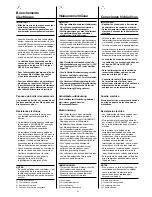
a
Photocatalytic filter tabs
a
Sedi alloggiamento filtri fotocatalitici
a
Languettes du filtre photocatalytique
a
Fotokatalytischer Filter
a
lengüetas fotocatalíticas
IMPORTANTE: Prima di ogni operazione di
manutenzione e prima di accedere alle parti interne
della
unità, togliere l’alimentazione elettrica.
Filtro aria
Controllare la pulizia del filtro almeno una volta al mese
o più spesso se l’unità è installata in zone polverose
.
Il filtro sporco diminuisce la portata d’aria e l’efficienza
dell’unità. Per accedere al filtro procedere come segue:
• spegnere l’unità;
• rimuovere le due viti poste alla base del mobile
con relative piastrine;
• abbassare le due guide e sfilare il filtro;
• pulire il filtro delicatamente con acqua e
detersivo, oppure con aspirapolvere;
• reinserire e posizionare il filtro nelle sue guide
mantenendo le sedi per alloggiamento filtri
fotocatalitici verso l’alto come indicato;
• riportare le guide nella posizione originale;
• riavvitare le viti con relative piastrine.
È raccomandabile pulire o eventualmente
sostituire il filtro prima della stagione invernale.
Scarico condensa
Durante la stagione estiva controllare che lo scarico
condensa sia libero da ostruzioni che potrebbero
provocare traboccamenti di acqua di condensa.
Batteria di scambio termico
All’inizio della stagione estiva ed invernale
controllare che le alette della batteria di scambio
termico non siano ostruite da corpi estranei quali
polvere, lanugine o altro. Pulire la batteria dopo
avere tolto la griglia di mandata dell’aria facendo
attenzione a non danneggiare le alette.
Motore
Il motore è lubrificato a vita. Non è pertanto
necessaria alcuna lubrificazione periodica.
IMPORTANT: Disconnect the mains power
supply prior to any maintenance operations or
prior to handling any internal parts of the unit.
Air filter
Check and make sure that the filter is cleaned at
least once a month or more often if unit is located
in a dusty room. A dirty filter reduces the air flow and
unit efficiency. To inspect filter proceed as follows:
• switch the unit OFF;
• loosen the two screws located at the base of
the unit and the corresponding plates;
• lower the two guides and withdraw filter;
• clean the filter gently with soapy water or with a
vacuum cleaner;
• reinsert and position the filter in the guides,
keeping the photocatalytic filter tabs upwards
as illustrated;
• return the filter guides to their original position;
• tighten the screws and associated plates.
It is advisable to clean and if necessary
replace the air filter before the winter season.
Condensate draining
During the summer season check that the
condensate drain is free from dust and lint that
could clog it, causing condensate water overflow.
Heat exchanger coil
At the beginning of any winter and summer
season it is advisable to check that the coil fins
are not clogged with dust, lint or other foreign
matter. Clean the heat exchanger after having
removed the supply grille, taking care not to
damage the fins.
Motor
The motor is permanently lubricated.
Therefore no periodical maintenance is required.
a
Sintomo / Possibile causa /
CONTROLLO
DA
EFFETTUARE
/ Soluzione
- Non funziona il display (Room Controller).
- Collegamento errato dei cavi di alimentazione
12V - GND SIGNAL.
-
VERIFICARE
CHE
I
COLLEGAMENTI
AL
+12V
ED
AL
GND
SIANO
CORRETTI
SIA
SUL
CRC
CHE
SULLA
MORSETTIERA
UNITÀ
(
VEDI
SCHEMI
ELETTRICI
).
- Dopo avere tolto l'alimentazione correggere il
problema sul cablaggio e riattivare l'alimentazione.
- Non funziona il display (Room Controller).
- Manca l'alimentazione.
-
CONTROLLARE
CHE
CI
SIA
L
'
ALIMENTAZIONE
PRINCIPALE
DELL
'
UNITÀ
.
LA
SCHEDA
HY
-
NEC
DEVE
FUNZIONARE
NORMALMENTE
(
LED
-
ROSSO
LAMPEGGIANTE
).
- Dopo avere verificato il cablaggio del “Room
Controller” riattivare l'alimentazione.
- L'unità non funziona anche se i cavi di
alimentazione sono collegati correttamente.
- Il “Room Controller” è danneggiato.
- Cambiare il “Room Controller”.
- L'unità non si avvia.
- Mancanza alimentazione, contatto finestra non
collegato o configurato in modo errato.
-
VERIFICARE
CHE
CI
SIA
ALIMENTAZIONE
,
COLLEGARE
O
CONFIGURARE
CORRETTAMENTE
IL
CONTATTO
FINESTRA
.
- Nelle unità provviste di riscaldatore elettrico,
quest'ultimo non funziona.
- Mancanza del Jumper con resistenza da 47 k
Ω
sul connettore J10 della scheda HY-NEC
(versioni alta potenza).
Mancanza del Jumper (cavallotto) 0
Ω
sul
connettore J10 della scheda HY-NEC (versioni
bassa potenza).
-
VERIFICARE
SE
PRESENTE
ILJUMPER
SUL
CONNETTORE
DELLA
SCHEDA
HY
-
NEC
.
- Collegare il Jumper da 0
Ω
(cavallotto) per
versioni con riscaldatore bassa potenza .
- Collegare il Jumper con resistenza da 47 k
Ω
per versioni con riscaldatore alta potenza .
Problemi e soluzioni
Symptom / Possible cause /
CHECKS TO BE CARRIED OUT
/ Remedy
- The display is not working (Room Controller).
- Incorrect connection of supply cables
12V - GND SIGNAL.
-
CHECK FOR CORRECT CONNECTIONS TO +12V AND GND
BOTH AT CRC AND UNIT TERMINAL BLOCK (SEE WIRING
DIAGRAMS).
- Disconnect power supply, correct the wiring
fault and switch on power supply again.
- The display is not working (Room Controller).
- No power supply.
-
CHECK FOR MAINS SUPPLY TO THE UNIT.
THE HY-NEC BOARD SHOULD OPERATE NORMALLY (RED
LED FLASHING).
- Check “Room Controller” wiring, then
switch on power supply again.
- The unit does not work when supply cables are
properly connected.
- Damaged “Room Controller”.
- Replace “Room Controller”.
- The unit does not start.
- No power supply, window contact disconnected
or wrongly configured.
-
CHECK FOR POWER SUPPLY, CONNECT WINDOW
CONTACT OR CONFIGURE CORRECTLY.
- Units fitted with electrical heater: the electrical
heater does not work.
- Missing 47 k
Ω
resistance jumper at the J10
connector of the HY-NEC board (high power
versions).
Missing 0
Ω
jumper at the J10 connector of the
HY-NEC board (low power versions).
-
CHECK FOR JUMPER AT THE HY-NEC BOARD CONNECTOR.
- Low-power heater versions: connect 0
Ω
jumper.
- High-power heater versions: connect 47 k
Ω
jumper.
Troubleshooting


