background image

II. HARDWARE INSTALLATION

IEZ / ITZV4  Motherboard User’s Manual

2-8

2-4

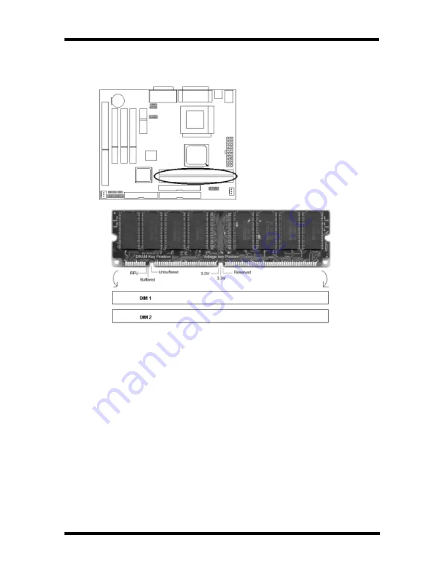
System Memory Installation

There are 2 pieces 168-pin DIMM (Dual Inline Memory Module) sockets on the

mainboard which support SDRAM and EDO DRAM memory.

There are 2x168-pin DIMM slots

(DIMM1, DIMM2) that allow you to

 install the system memory max

 up to 512MB SDRAM.

To ensure reliability, it is recommended to use PC 100 SDRAM or PC 133 SDRAM

for your high clock SDRAM performance requirement.

If you are using low clock SDRAMs, you should set the SDRAM clock option of

the BIOS’s Chipset Feature Setup to HCLK-33 to ensure stability.

 DIMM Sizes supported: 

8MB, 16MB, 32MB, 64MB, 128MB, 256MB.

8MB, 16MB, 32MB, 64MB, 128MB.

8MB, 16MB, 32MB, 64MB, 128MB.

8MB, 16MB, 32MB, 64MB, 128MB.

8MB, 16MB, 32MB, 64MB, 128MB.

Total Memory Size = DIMM1 + DIMM2, maximum up to 512MB.

Содержание IEZ

Страница 1: ...IEZ ITZV4 Micro ATX Intel 810E Micro ATX Intel 810 Socket 370 Motherboard User s Guide Model IEZ ITZV4 Manual Version English version 1 0 Release Date JAN 14 2000...

Страница 2: ...this publication are subject to change This company reserves the right to alter the contents of this publication at any time and without notice The contents of this publication may contain inaccuracie...

Страница 3: ...urer s instructions may cause harmful interference to radio communication However there is no guarantee that interference will not occur in a particular installation If this equipment does cause harmf...

Страница 4: ...Setup 3 2 3 3 Adcanced BIOS Features 3 4 3 4 Advanced Chipset Features 3 8 3 5 Integrated Peripherals 3 11 3 6 Power Management Setup 3 15 3 7 PnP PCI Configurations 3 18 3 8 PC Health Status 3 19 3...

Страница 5: ...kage contains the following items Please inspect the package contents and confirm that every thing is there If anything is missing or damaged call your vendor for instructions before operating The Pac...

Страница 6: ...pabilities port Floppy Interface Support drivers inches format with 3 5 inches 720KB 1 44MB 2 88MB 5 25 inches 360KB 1 2MB Ide Interface Dual Ide Interface support 4 x IDE HDD or CDROM Support PIO Mod...

Страница 7: ...yout Motherboard Layout Motherboard Layout Motherboard Layout I Product Information IEZ ITZV4 Motherboard User s Manual 1 2 Jumpers Jumpers Jumpers Jumpers Jumpers 1 JP2 CPU Clock Frequency 2 JP1 Clea...

Страница 8: ...IDE1 Primary IDE Connector 2 IDE2 Secondary IDE Connector 3 Floppy Floppy Drive Connector 4 Panel PowerOn ATX Power on Reset Reset Swithch Connector HDD Led HDD Led Connector Power Led ATX Power Led C...

Страница 9: ...e jumpers on the mainboard 2 1 1 CMOS Clear Setting JP1 Clear CMOS Clear CMOS Normal Default To clear CMOS please follow the steps below 1 Power off the system and unplug the chassis AC power cord 2 S...

Страница 10: ...ion of the system chassis for a few seconds to discharge any built up static electricity Handle add in cards and modules by the edges or mounting bracket CPU Setting After installing the CPU you must...

Страница 11: ...43 Short Open Short Open 145 00 36 25 Short Open Open Short 133 73 33 43 Short Open Open Open 137 33 34 33 Open Short Short Short 140 00 35 00 Open Short Short Open 140 00 46 67 Open Short Open Short...

Страница 12: ...ector 2 pins ATX Power Switch Connector 2 pins 2 2 2 Power Connector Connect the 20 pin ATX power supply cable to this power connector Make sure the right plug in direction and the power supply is off...

Страница 13: ...n below The fan connectors are marked as SYS FAN CPU FAN on the motherboad 2 2 4 PS 2 Mouse and Keyboard Connectors Connect the PS 2 mouse and keyboard to the onboard 6 pin Mini Din connector shown as...

Страница 14: ...rked as VGA to your system monitor or other VGA compatible devices Connect your local printer to the onboard 25 pin printer connector marked shown as below COM1 VGA PRINTER 2 2 7 Floppy Drive Connecto...

Страница 15: ...s the figure shown above Each IDE channel either Primary or Secondary supports two IDE devices which must be set differently to master mode and slave mode 2 3 Game Audio Connector and CD IN Connectors...

Страница 16: ...m memory max up to 512MB SDRAM To ensure reliability it is recommended to use PC 100 SDRAM or PC 133 SDRAM for your high clock SDRAM performance requirement If you are using low clock SDRAMs you shoul...

Страница 17: ...tem to try again by turning it OFF then ON or pressing the RESET button on the system case You may also restart by simultaneously pressing Ctrl Alt and Delete keys 3 1 BIOS Setup Main Menu Once you en...

Страница 18: ...0 Save ESC Exit F1 General Help F5 Previous Values F6 Fail safe defaults F7 Optimized Defaults IEZ ITZV4 Motherboard User s Manual 3 2 III CMOS SETUP UTILITY Standard CMOS Features Date mm dd yy Tim e...

Страница 19: ...city Capacity Capacity Capacity Capacity Capacity Capacity Capacity Capacity Capacity Disk drive capacity approximated Note that this size Auto display your is usually slightly greater thanthe size of...

Страница 20: ...l But Keyboard 3 3 Advanced BIOS Features This section allows you to configure your system for basic operation CMOS Setup Utility Copyright 1984 2000 Award Software Advanced BIOS Features Item Help Vi...

Страница 21: ...Boot Other Device First Second Third Boot Other Device First Second Third Boot Other Device First Second Third Boot Other Device First Second Third Boot Other Device First Second Third Boot Other Devi...

Страница 22: ...e A20 Fast lets chipset control Gate A20 Fast Default Fast Default Fast Default Fast Default Fast Default Fast T T T T Typematic Rate Setting ypematic Rate Setting ypematic Rate Setting ypematic Rate...

Страница 23: ...rrect password is not entered at the prompt Default Setup Default Setup Default Setup Default Setup Default Setup OS Select for DRAM 64MB OS Select for DRAM 64MB OS Select for DRAM 64MB OS Select for...

Страница 24: ...o read from or refreshed Default 3 Default 3 Default 3 Default 3 Default 3 3 4 Advanced Chipset Features This item allows you to configure the system based on the specific features of the chipset This...

Страница 25: ...ystem performance Disabled Default Disabled Default Disabled Default Disabled Default Disabled Default Disabled Memory Hole At 15M 16M Memory Hole At 15M 16M Memory Hole At 15M 16M Memory Hole At 15M...

Страница 26: ...y clock periods 3 2 Default 3 Default 3 Default 3 Default 3 Default 3 Paging Mode Control Paging Mode Control Paging Mode Control Paging Mode Control Paging Mode Control Paging Mode Control Paging Mod...

Страница 27: ...ripheral controller contains Disabled an IDE interface with support for two IDE channels Select Enabled to activate each channel separately Default Enabled Default Enabled Default Enabled Default Enab...

Страница 28: ...io Modem AC 97 Audio Modem AC 97 Audio Modem AC 97 Audio Modem This item allows you to decide to enable Auto disable the 810 chipset family to support Disabled AC 97 audio modem Default Auto Default A...

Страница 29: ...1 2 Onboard Serial Port 1 2 Onboard Serial Port 1 2 Onboard Serial Port 1 2 Onboard Serial Port 1 2 Onboard Serial Port 1 2 Onboard Serial Port 1 2 Onboard Serial Port 1 2 Onboard Serial Port 1 2 Onb...

Страница 30: ...rt Address Game Port Address Game Port Address Game Port Address Game Port Address Game Port Address Game Port Address Select an address for game port Disabled 201 209 Default 201 Default 201 Default...

Страница 31: ...Management Setup allows you to configure your system effectively save energy while operating in a manner consistent with your own style of computer use ACPI Function ACPI Function This opotion allows...

Страница 32: ...tem Stop Grant suspend PwrOn Suspend Default PwrOn Suspend Default PwrOn Suspend Default PwrOn Suspend Default PwrOn Suspend Default PwrOn Suspend Modem Use IRQ Modem Use IRQ Modem Use IRQ Modem Use I...

Страница 33: ...Disabled Default Disabled Default Disabled Default Disabled Default Disabled Default Disabled Primary Secondary IDE 0 IDE 1 Primary Secondary IDE 0 IDE 1 Primary Secondary IDE 0 IDE 1 Primary Seconda...

Страница 34: ...ation Data Reset Configuration Data Normally you leave this field Disabled Select Enabled Enabled to reset Extended System Configuration Data ESCD Disabled when you exit Setup if you have installed a...

Страница 35: ...uency V Frequency V Frequency V Frequency Voltage Control oltage Control oltage Control oltage Control oltage Control CMOS Setup Utility Copyright 1984 2000Award Software Frequency Voltage Control Aut...

Страница 36: ...Disabled EMI Enabling pulse spectrum spread modula tion changes the extreme values from spikes to flat curves thus reducing EMI This benefit may in some cases be outweighed by problems with timing cr...

Страница 37: ...P C H e a lth S ta tu s E xit W it h o u t S a v in g E S C Q u it F 1 0 S a v e E xit S e t u p S e le c t Ite m L o a d F a il S a fe D e fa u lts L o a d F a il S a fe D e fa u lts Y N N IEZ ITZV4...

Страница 38: ...d before boot or access to setup The main difference between Supervisor Password and User Password is the privilege Because Supervisor Password allows you to modify all CMOS setup but User password on...

Страница 39: ...ogram Driver files location Driver files location Driver files location Driver files location Driver files location Intel VGA Driver Program Video 810VGA 4 2 4 2 4 2 4 2 4 2 Intel chipset Driver Progr...

Отзывы: