background image

Operating Instructions Safety Systems
MGB2-L1…-BR.-… / MGB2-L2…-BR.-… and MGB2-L1…-BP.-… / MGB2-L2…-BP.-…

8

(Translation of the original operating instructions) 2500233-01-05/19

Important!


Ì

The user is responsible for the proper integration of the device into a safe overall system. For this 

purpose, the overall system must be validated, e.g. in accordance with EN ISO 13849-2.


Ì

Correct use requires observing the permissible operating parameters (see chapter 16. Technical 

data on page 48).


Ì

If a data sheet is included with the product, the information on the data sheet applies.

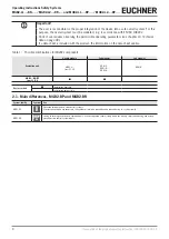
Table 1:  Possible combinations for MGB2 components

Evaluation unit

Handle module

Submodules

Submodules

MGB2-H-...

from V1.0.0

MSM-.-P-...

MSM-.-N-...

MSM-.-K-...

MSM-.-R-...

MGB2…BR/BP

from V1.0.0

Key to symbols

Combination possible

Combination not possible

2.1.  Main differences, MGB2-BP and MGB2-BR

System family

Symbol

Use

MGB2-BP

BP

Optimized for operation in safe control systems.

If series connection is not necessary, the number of terminals required can be reduced using this system family.

MGB2-BR

BR

Linking of several guards on one shutdown path. As a consequence several safety doors can be very simply polled using one evalua-

tion unit or two control system inputs. 

Содержание MGB2-BP Series

Страница 1: ...EN Operating Instructions Safety Systems MGB2 L1 BR MGB2 L2 BR MGB2 L1 BP MGB2 L2 BP from V1 0 0 ...

Страница 2: ...n MGB2 L2 12 7 System overview 13 7 1 Locking module MGB2 L 13 7 2 Handle module MGB2 H 13 7 3 Escape release MGB E optional 14 7 4 Dimension drawing 15 8 Manual release 16 8 1 Auxiliary release and auxiliary key release can be retrofitted 16 8 1 1 Actuating auxiliary release 16 8 1 2 Actuating auxiliary key release 16 8 2 Emergency unlocking can be retrofitted 17 8 2 1 Actuating emergency unlocki...

Страница 3: ...ing 33 13 7 3 Activating release monitoring 33 13 8 Notes on operation with control systems 34 13 9 Connection of guard locking control 35 13 9 1 Guard locking control for devices with IMM connection 35 13 9 2 Guard locking control for devices without IMM connection 35 13 10 Terminal assignment and contact description 36 13 11 Terminal assignment submodule with plug connector M23 37 13 12 Operatio...

Страница 4: ...he original operating instructions 2500233 01 05 19 17 Troubleshooting and assistance 51 17 1 Resetting errors 51 17 2 Help on troubleshooting in the Internet 51 17 3 Help on mounting in the Internet 51 17 4 Application examples 51 18 Service 51 19 Inspection and service 52 20 Declaration of conformity 53 ...

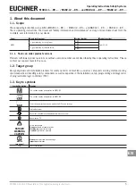
Страница 5: ...operating instructions Please contact our support team in this case 1 2 Target group Design engineers and installation planners for safety systems on machines as well as setup and servicing staff possessing special expertise in handling safety components as well as expertise in the installation setup programming and diagnostics of programmable logic controllers PLC 1 3 Key to symbols Symbol depict...

Страница 6: ...tents Safety Information and Maintenance Safety Sys tem MGB2 BR MGB2 BP from V1 0 0 Basic information for safe setup and service Operating Instructions 2500233 this document I n t e r n e t www Possibly enclosed data sheets Item specific information about deviations or additions Important Always read all documents to gain a complete overview of safe installation setup and use of the device The doc...

Страница 7: ...command must be issued For exceptions refer to EN ISO 12100 or relevant C standards With inactive guard locking monitoring the following applies In combination with a movable guard and the machine control this safety component prevents dangerous machine functions from occurring while the guard is open A stop command is triggered if the guard is opened during the dangerous machine function With ina...

Страница 8: ...with the product the information on the data sheet applies Table 1 Possible combinations for MGB2 components Evaluation unit Handle module Submodules Submodules MGB2 H from V1 0 0 MSM P MSM N MSM K MSM R MGB2 BR BP from V1 0 0 Key to symbols Combination possible Combination not possible 2 1 Main differences MGB2 BP and MGB2 BR System family Symbol Use MGB2 BP BP Optimized for operation in safe con...

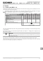
Страница 9: ...er 16 Technical data on page 48 Activation of guard locking Ì Ì Safety function If the device is used as guard locking for personnel protection control of guard locking must be regarded as a safety function The safety level of guard locking control is determined by the device PFHD int and by the external control e g PFHD ext of the standstill monitor PFHDext Guardlocking Device e g standstill moni...

Страница 10: ...on or due to bypassing tampering Safety components fulfill a personnel protection function Ì Ì Safety components must not be bypassed turned away removed or otherwise rendered ineffec tive On this topic pay attention in particular to the measures for reducing the possibility of bypass ing according to EN ISO 14119 2013 section 7 Ì Ì The switching operation is allowed to be triggered only by the in...

Страница 11: ...E Guard locking active TRUE Not relevant TRUE Not relevant In case of series connection Signal available from the upstream switch on the safety inputs FI1A and FI1B In case of separate operation DC 24 V present at the safety inputs FI1A and FI1B TRUE TRUE Not relevant Not relevant FO1A and FO1B are ON The locking module detects the position of the guard and the position of the bolt tongue The posi...

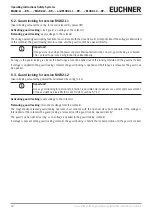
Страница 12: ...gue cannot be pulled out of the locking module and the guard is locked If voltage is applied to the guard locking solenoid the guard locking is opened and bolt tongue is released The guard can be opened 6 3 Guard locking for version MGB2 L2 Guard locking actuated by power ON and released by spring force Important Use as guard locking for personnel protection is possible only in special cases after...

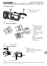
Страница 13: ...ith guard locking LED indicator for submodule in SLOT 1 5 Submodule in SLOT 1 configuration example 6 Auxiliary marking for correct align ment in relation to the handle module 7 Locking arm Terminals X1 X4 Internal reset Notice Depending on the version additional controls and indicators may be integrated into the cover and a mounting plate can be included See enclosed data sheet Figure 2 Locking m...

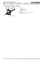
Страница 14: ...riginal operating instructions 2500233 01 05 19 7 3 Escape release MGB E optional 1 2 3 4 Key 1 Door handle 2 Housing 3 Actuation axis 8 x 8 mm different lengths available 4 Protective sleeve Notice Depending on the version a mounting plate can be included See enclosed data sheet Figure 4 Escape release MGB E ...

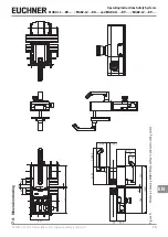
Страница 15: ...ions Operating Instructions Safety Systems MGB2 L1 BR MGB2 L2 BR and MGB2 L1 BP MGB2 L2 BP EN 7 4 Dimension drawing 40 15 40 155 4 130 114 114 2 110 59 62 3 22 2 40 130 63 52 5 155 4 42 115 5 289 Figure 5 Dimension drawing MGB2 fitted without optional mounting plates ...

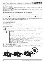
Страница 16: ...ocking is released DIP OFF ON Ì Ì When release monitoring is active the system enters into a latching fault when the auxiliary release is actuated See System status table signal sequence incorrect status DIA red Lock flashes 1 time Ì Ì The system might not enter into a latching fault if the auxiliary release is actuated very slowly Important Ì Ì The auxiliary release must be reset at the control s...

Страница 17: ...Actuating emergency unlocking Ì Ì Turn emergency unlocking clockwise until it clicks into place Guard locking is released To reset press the snap in bolt inward using a small screwdriver or similar tool and turn the emergency unlocking back The safety outputs are switched off when the emergency unlocking is actuated Use the safety outputs to generate a stop command The monitoring output OL is swit...

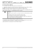
Страница 18: ...ted see chapter 17 Troubleshooting and assistance on page 51 Important Ì Ì It must be possible to actuate the escape release manually from inside the protected area without tools Ì Ì It must not be possible to reach the escape release from the outside Ì Ì The bolt tongue must not be under tensile stress during manual release Ì Ì The escape release meets the requirements of Category B according to ...

Страница 19: ...axis and protective sleeve and shorten to required length 45 mm 54 mm 62 mm Standard escape release with 107 mm axis order no 100465 and extended actuation axis order no 106761 Use extended actuation axis and protective sleeve and shorten to required length 50 mm 59 mm 67 mm Standard escape release with 107 mm axis order no 100465 and extended actuation axis order no 106761 Use extended actuation ...

Страница 20: ...f the installation depth and the guard material Locking module Handle module Locking module Handle module Surface mounting Flush installation Operating distance Operating distance Tip Ì Ì You will find an animation on the mounting process at www euchner com Ì Ì The pushbuttons and indicators can be customized using replaceable color covers and labels For mounting steps see Figure 9 and Figure 12 t...

Страница 21: ...9 Translation of the original operating instructions Operating Instructions Safety Systems MGB2 L1 BR MGB2 L2 BR and MGB2 L1 BP MGB2 L2 BP EN M6 T10 Figure 9 Installation example for door hinged on the right general view ...

Отзывы: