ETOP ITX-E16 Скачать руководство пользователя страница 87


ITX-E16 User`s Manual 


79


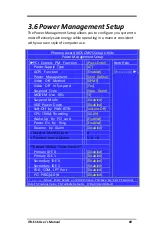
3.8 PC Health Status 

This section helps you to get more information about your system 
including CPU temperature, FAN speed and voltages. It is 
recommended that you contact with your motherboard supplier to 
get proper value about your setting of the CPU temperature. 
 

Phoenix-Award BIOS CMOS Setup Utility 

PC Health Status 

CPU Warning  Temperature 

[Disabled] 

Current System Temp. 

40

C / 107

Current CPU   Temperature: 

40

C / 100

CPU   FAN   Speed 

0 RPM 

CHASSIS  Fan  Speed 

7670 RPM 

Vcore  

1.20V 

+1.5V 

1.52V 

+3.3V 

3.47V 

+5V 

5.16V 

+12V 

12.22V 

-12V 

-12.44V 

VBAT(V) 

3.32V 

5VSB(V) 

5.04V 

Shutdown Temperature 

[Disabled] 


Item Help 
 

Menu Level 


↑↓←


Move   Enter: Select   +/-/PU/PD: Value   F10:Save  Esc: Exit  

F1:General Help F5:Previous Value   F6:Fail-Safe Defaults    F7:Optimized Default 


CPU Warning Temperature 

Select the CPU over-heated warning temperature. 
The  choice:  Disabled 

(default)

,  50

C/122

F,  53

C/127

F,  56

C/133

F, 

60

C/140

F, 63

C/145

F, 66

C/151

F, 70

C/158

F.


Current System Temp 

Show System Temperature. 
 

Current CPU Temperature 

Shows Board Temperature 


Содержание ITX-E16

Страница 1: ...ITX E16 Intel Core 2Duo 945GME Mini ITX Main Board User s Manual Version 1 0...

Страница 2: ...will the original manufacturer be liable for direct indirect special exemplary incidental incidental or consequential damages resulting from any defect or omission in this manual even if advised of po...

Страница 3: ...tion 12 COM2MODE RS232 RS422 RS485 12 LCDPWR LCD PANEL Power Selection 13 2 2 CONNECTORS ON THE ITX E16 14 Connector Locations on the ITX E16 15 AUDIO Connector 16 INT_AUDIO Connector 16 SPDIF Connect...

Страница 4: ...igurations 36 PC Health Status 36 Frequency Voltage Control 36 Load Fail Safe Defaults 36 Load Optimized Defaults 36 Set Supervisor User Password 36 Save Exit Setup 36 Exit Without Saving 36 3 2 STAND...

Страница 5: ...ry Frequency 50 SLP_S4 Assertoin Width 51 System BIOS Cacheable 51 Video BIOS Cacheable 51 Memory Hole At 15M 16M 51 On Chip Frame Buffer Size 51 DVMT Mode 51 DVMT FIXED Memory Size 51 Boot Display 52...

Страница 6: ...Port 3 68 Serial Port 3 Use IRQ 68 Onboard Serial Port 4 68 Serial Port 4 Use IRQ 68 Onboard Serial Port 5 68 Serial Port 5 Use IRQ 68 Onboard Serial Port 6 68 Serial Port 6 Use IRQ 68 Watch Dog Time...

Страница 7: ...nt 78 Maximum Payload Size 78 3 8 PC HEALTH STATUS 79 CPU Warning Temperature 79 Current System Temp 79 Current CPU Temperature 79 CPU FAN Speed 80 CHASSIS Fan Speed 80 Shutdown Temperature 80 3 9 FRE...

Страница 8: ...Contents viii ITX E16 User s Manual This page is intentionally left blank...

Страница 9: ...Introduction This manual is designed to give you information on the ITX E16 Single Board Computer card The topics covered in this manual are as follows Features Specification Jumper setting and Connec...

Страница 10: ...2 ITX E16 User s Manual Chapter 1 Features Specifications FEATURES 3 SPECIFICATIONS 4...

Страница 11: ...al 24 bits LVDS TV OUT Dual Independent display and rotation supported by drivers Dual GbE LAN design maximized the communication bandwidth for both internet and intranet connection Root Boot and Wake...

Страница 12: ...nnector for Dual 18 24 bits LVDS LCD displays One 20 pins 1 25mm pitch connector for DVI displays One 5 pins JST connector for Inverter power and brightness control Super I O Winbond 83627HF LPC I F S...

Страница 13: ...ne standard 44 pins Box header to support 2 5 HDD or DOM Flash Disk One Compact Flash II socket shared with PIDE Channel One jumper to select as Master or Slave device Two SATA connectors from ICH7M s...

Страница 14: ...Cards Power Connector Support both AT mode and ATX mode operation Selectable by jumper One Standard ATX 20 pins power connector for system power One ATX 12V 4 pins connector for CPU power input Softwa...

Страница 15: ...ITX E16 User s Manual 7 Chapter 2 Jumper setting Connectors 2 1 JUMPERS ON THE ITX E16 8 2 2 CONNECTORS ON THE ITX E16 14...

Страница 16: ...uration for your needs contact your dealer or sales representative The following table lists the jumpers on ITX E16 and their respective functions Jumper Locations on the ITX E16 9 JP1 JP2 JP3 FSB SPD...

Страница 17: ...ITX E16 User s Manual 9 Jumper Locations on the ITX E16...

Страница 18: ...JP1 JP2 JP3 667M JP1 JP2 JP3 JP4 Clear CMOS RAM Data This 3 pin Jumper allows the user to disconnect the built in 3V battery power to clear the information stored in the CMOS RAM To clear the CMOS dat...

Страница 19: ...Channel Master device or Slave device Master Slave JP5 JP5 JP6 JP7 COM Power Selection JP6 JP7 can be used to select the COM supple power 5V Ring IN or 12V JP6 COM1 Pin9 power or Ring IN JP7 COM2 pin...

Страница 20: ...rotocols include RS232 RS422 and RS485 while COM3 COM4 COM5 and COM6 support diffused RS232 protocol The Protocols of COM2 can be set up through jumpers COM2MODE COM2 Protocols selection The pin out f...

Страница 21: ...CDPWR can be used to select the Panel LCD supple power 3 3V or 5V The default setting is on 3 3V User need to check the LCD panel spec and adjust this jumper to make Panel work in specified power rail...

Страница 22: ...IF Connector 17 CD_IN Connector 17 DIO Connector 18 USB12 34 Connectors 18 INT_VGA Connector 19 SATA1 2 Connectors 19 VGA Connector 20 LAN GbE USBx2 Connectors 20 LAN1 2 GbE Connectors 21 System FAN C...

Страница 23: ...ITX E16 User s Manual 15 Connector Locations on the ITX E16...

Страница 24: ...rophone to MIC In jack Audio sources devices like CD ROM walkman and etc can be connected to Lin In jack INT_AUDIO Connector Signal Name Pin Pin Signal Name LINE IN_L 1 2 LINE IN_R GND 3 4 GND LINE OU...

Страница 25: ...llow digital instead of analog sound input or output Signal Name Pin Pin Signal Name VCC 1 2 NC SPDIFO 3 4 SPDIFI GND 5 6 GND CD_IN Connector CD_IN connector is designed for wire the CD_ROM audio sign...

Страница 26: ...l bits are 5V tolerant Signal Name Pin Pin Signal Name GND 1 2 5V DIO_0 3 4 DIO_4 DIO_1 5 6 DIO_5 DIO_2 7 8 DIO_6 DIO_3 9 10 DIO_7 USB12 34 Connectors The following table shows the pin outs of the USB...

Страница 27: ...al Video A D board connection The pin out is listed as below Signal Name Pin Pin Signal Name RED 1 2 GND GREEN 3 4 GND BLUE 5 6 GND HSYNC 7 8 DDC_DATA VSYNC 9 10 DDC_CLK SATA1 2 Connectors Pin Signal...

Страница 28: ...J45 ports and USB Type A ports on the Combo RJ45 USB connector Before you connect your device s into USB connector s please make sure your device s such as USB keyboard mouse scanner zip speaker and e...

Страница 29: ...ut assignments of this connector and its corresponding input jack Pin Signal Name 1 MDI0 2 MDI0 3 MDI1 4 MDI1 5 MDI2 6 MDI2 7 MDI3 8 MDI3 System FAN Connector This is a 3 pin header for the system fan...

Страница 30: ...activity The Orange Green Dual color LED on the left hand side indicates the operation mode i e 10Base T 100Base T or 1000Base T LNK ACT STATUS YELLOW Link OFF Disconnected FLASH Packets TX RX SPEED M...

Страница 31: ...3 3V 12 12V 3 GND 13 GND 4 5V 14 PSON 5 GND 15 GND 6 5V 16 GND 7 GND 17 GND 8 PWROK 18 5V 9 5VSB 19 5V 10 12V 20 5V INT_KBMS Connector INT_KBMS is for internal input devices or MSR connection The pin...

Страница 32: ...users need to connect trough a PS 2 1 to 2 Y cable and plug into this Mini Din connector All the ITX E16 boards come with a Y cable Contact with your dealer if the Y cable is missing Pin Signal Name 1...

Страница 33: ...ector acts as the Power Supply On Off Switch on the E16 main board When pressed the switch will force the Main board to power on When pressed again it will force the main board to power off PWR BTN Pi...

Страница 34: ...nd RESET Switch The reset switch allows the user to reset the system without turning the main power switch off and then on Orientation is not required when making a connection to this header RESET Pin...

Страница 35: ...4 3 GND LCDVDD 5V 3 3V 6 5 LCDVDD 5V 3 3V GND 8 7 GND BCKLITE_ON 10 9 BRIGHTNES LVDS_GND 12 11 LVDS_GND CHB_TX0 14 13 CHA_TX0 CHB_TX0 16 15 CHA_TX0 LVDS_GND 18 17 LVDS_GND CHB_TX1 20 19 CHA_TX1 CHB_T...

Страница 36: ..._PLUG 18 17 GND VCC 20 19 VCC LPT Port The LPT parallel port is a standard DSUB 26 pins Female connector It can be configured as EPP or ECP or SPP mode Signal Name Pin Pin Signal Name Strobe 1 14 AUTO...

Страница 37: ...10 GND GND 11 12 GND VCC 13 14 GND GND 15 16 GND GND 17 18 PDA2 PDA1 19 20 PDA0 PDD0 21 22 PDD1 PDD2 23 24 N C N C 25 26 N C PDD11 27 28 PDD12 PDD13 29 30 PDD14 PDD15 31 32 PCS3 N C 33 34 PDIOR PDIOW...

Страница 38: ...ta set ready 7 RTS Request to send 8 CTS Clear to send 9 5V Ring IN or 12V COM2 6 Serial Ports COM2 COM6 a 10 pins header connector is the onboard COM2 COM6 serial port of the E16 The following table...

Страница 39: ...OM3 COM4 COM5 serial port of the E16 The following table shows its pin assignments Pin RS232 Mode Signal Name 1 DCD Data carrier detect 2 RXD Receive data 3 TXD Transmit data 4 DTR Data terminal ready...

Страница 40: ...ost data 3 11 12 Host data 12 Host data 2 13 14 Host data 13 Host data 1 15 16 Host data 14 Host data 0 17 18 Host data 15 Ground 19 20 Key DRQ 21 22 Ground Host IOW 23 24 Ground Host IOR 25 26 Ground...

Страница 41: ...1 MAIN MENU 35 3 2 STANDARD CMOS FEATURES 37 3 3 ADVANCED BIOS FEATURES 42 3 4 ADVANCED CHIPSET FEATURES 49 3 5 INTEGRATED PERIPHERALS 53 3 6 POWER MANAGEMENT SETUP 69 3 7 PNP PCI CONFIGURATION 75 3...

Страница 42: ...system performance that can destabilize operation We urge you to proceed with caution When the system is powered on use the bios set program when you start up your system reconfiguring your system or...

Страница 43: ...Exit Setup Exit Without Saving Esc Quit Select Item F10 Save Exit Setup Load Optimized Defaults Figure 1 Note that a brief description of each highlighted selection appears at the bottom of the screen...

Страница 44: ...y voltage control Load Fail Safe Defaults Use this menu to load the BIOS default values for the minimal stable performance for your system to operate Load Optimized Defaults Use this menu to load the...

Страница 45: ...CMOS Setup Utility Standard CMOS Features Date mm dd yy Mon Apr 28 2008 Time hh mm ss 15 35 35 IDE Channel 0 Master None IDE Channel 0 Slave None IDE Channel 1 Master None IDE Channel 1 Slave None Dr...

Страница 46: ...menu of detailed options D IDE Channel 1 Slave Options are in its sub menu Press Enter to enter the sub menu of detailed options Drive A Drive B None 360K 5 25 in 1 2M 5 25 in 720K 3 5 in 1 44M 3 5 i...

Страница 47: ...enu Phoenix Award BIOS CMOS Setup Utility IDE Channel 0 Master IDE HDD Auto Detection Press Enter IDE Channel 0 Master Auto Access Mode Auto Capacity 0 MB Cylinder 0 Head 0 Precomp 0 Landing Zone 0 Se...

Страница 48: ...the number of cylinders heads etc Note PRECOMP 65535 means NONE Access Mode CHS LBA Large Auto Choose the access mode for this hard disk Capacity Auto Display your disk drive size Disk drive capacity...

Страница 49: ...CGA 80 Power up in 80 column mode MONO For Hercules or MDA adapters Halt On This field determines whether the system will halt if an error is detected during power up All errors Whenever the BIOS det...

Страница 50: ...Enabled Quick Power On Self Test Enabled First Boot Device Hard Disk Second Boot Device CDROM Third Boot Device LS120 Boot Other Device Enabled Swap Floppy Drive Disabled Boot Up Floppy Seek Enabled...

Страница 51: ...Help F5 Previous Value F6 Fail Safe Defaults F7 Optimized Default Figure 5 Delay Prior to Thermal Delay Prior To Thermal is set at 16 minutes as default which means the board will wait 16 minutes bef...

Страница 52: ...hen press to move it up or to move it down the list Press ESC to exit this menu Move Enter Select PU PD Value F10 Save Esc Exit F1 General Help F5 Previous Value F6 Fail Safe Defaults F7 Optimized Def...

Страница 53: ...or hard disk partition table Disabled No warning message will appear when anything attempts to access the boot sector or hard disk partition table default CPU L1 L2 Cache These two categories speed up...

Страница 54: ...when it failed to load from the three devices above The choice Enabled default Disabled Swap Floppy Drive If the system has two floppy drives choose Enabled to assign physical drive B to logical drive...

Страница 55: ...ice Rate and Delay Typematic Rate Chars Sec Sets the number of times a second to repeat a keystroke when you hold the key down The choice 6 default 8 10 12 15 20 24 30 Typematic Delay Msec Sets the de...

Страница 56: ...o enter password Do not type anything and just press Enter it will disable security Once the security is disabled the system will boot and you can enter Setup freely APIC Mode This setting allows to e...

Страница 57: ...red that data was being lost while using your system Phoenix Award BIOS CMOS Setup Utility Advanced Chipset Features DRAM Timing Selectable By SPD x CAS Latency Time Auto x Dram RAS to CAS Delay Auto...

Страница 58: ...ble Leave this on the default setting The choice 5 4 3 6 Auto default DRAM RAS to CAS Delay In order to improve performance certain space in memory is reserved for PISA cards This memory must be mappe...

Страница 59: ...rmance However if any program writes to this memory area a system error may occur The choice Enabled Disabled default Memory Hole At 15M 16M Enabling this feature reserves 15 MB to 16 MB memory addres...

Страница 60: ...12 13 14 15 16 TV Standard The choice Off default NTSC PAL SECAM Video Connector The choice Automatic default Composite Component Both TV Format The choice Auto defau lt NTSC_M NTSC_M_J NTSC_433 NTSC...

Страница 61: ...Onboard Serial Port 3 3E8 Serial Port 3 Use IRQ IRQ3 Onboard Serial Port 4 2E8 Serial Port 4 Use IRQ IRQ4 Onboard Serial Port 5 4F8 Serial Port 5 Use IRQ IRQ5 Onboard Serial Port 6 4E8 Serial Port 6 U...

Страница 62: ...automatic detection of the optimal number of lock read writes per sector the drive can support Move Enter Select PU PD Value F10 Save Esc Exit F1 General Help F5 Previous Value F6 Fail Safe Defaults...

Страница 63: ...themselves Your system supports five modes 0 default to 4 which primarily differ in timing When Auto is selected the BIOS will select the best available mode after checking your drive Auto The BIOS wi...

Страница 64: ...SATA Mode IDE On Chip Serial ATA Auto x SATA PORT Speed Settings Disable x PATA IDE Mode Secondary x SATA Port PO P2 is Primary Item Help Menu Level If your IDE hard drive suppers block mode select E...

Страница 65: ...dary Master PIO Auto IDE Secondary Slave PIO Auto IDE Secondary Master UDMA Auto IDE Secondary Slave UDMA Auto On Chip Serial ATA Setting x SATA Mode IDE On Chip Serial ATA Auto x SATA PORT Speed Sett...

Страница 66: ...Mode x SATA PORT Speed Settings Disable PATA IDE Mode Secondary x SATA Port PO P2 is Primary Item Help Menu Level If your IDE hard drive suppers block mode select Enabled for automatic detection of th...

Страница 67: ...On Chip Serial ATA Setting SATA Mode IDE On Chip Serial ATA Enhanced Mode SATA PORT Speed Settings Disable x PATA IDE Mode Secondary x SATA Port PO P2 is Primary Item Help Menu Level If your IDE hard...

Страница 68: ...Master UDMA Auto IDE Secondary Slave UDMA Auto On Chip Serial ATA Setting SATA Mode IDE On Chip Serial ATA SATA Only x SATA PORT Speed Settings Disable x PATA IDE Mode Secondary x SATA Port PO P2 is...

Страница 69: ...Serial Bus USB controller and you have USB peripherals The choice Enabled default Disabled USB 2 0 Controller This entry is for disable enable USB2 0 controller only The BIOS itself may may not have...

Страница 70: ...ct EPP1 7 x ECP Mode Use DMA 3 PWRON After PWR Fail Off Item Help Menu Level Move Enter Select PU PD Value F10 Save Esc Exit F1 General Help F5 Previous Value F6 Fail Safe Defaults F7 Optimized Defaul...

Страница 71: ...D TxD Active Hi Lo IR Transmission Delay Enabled UR2 Duplex Mode Half Onboard Parallel Port 378 IRQ7 Parallel Port Mode SPP x EPP Mode Select EPP1 7 x ECP Mode Use DMA 3 PWRON After PWR Fail Off Item...

Страница 72: ...nal ECP Sets the parallel port up as an Enhanced Capabilities Port This setting requires the use of a DMA channel If Parallel Port Mode Select is SPP and Normal will show Phoenix Award BIOS CMOS Setup...

Страница 73: ...D TxD Active Hi Lo IR Transmission Delay Enabled UR2 Duplex Mode Half Onboard Parallel Port 378 IRQ7 Parallel Port Mode EPP EPP Mode Select 1 7 x ECP Mode Use DMA 3 PWRON After PWR Fail Off Item Help...

Страница 74: ...de Half Onboard Parallel Port 378 IRQ7 Parallel Port Mode ECP x EPP Mode Select 1 7 ECP Mode Use DMA 3 PWRON After PWR Fail Off Item Help Menu Level Move Enter Select PU PD Value F10 Save Esc Exit F1...

Страница 75: ...DMA 3 PWRON After PWR Fail Off Item Help Menu Level Move Enter Select PU PD Value F10 Save Esc Exit F1 General Help F5 Previous Value F6 Fail Safe Defaults F7 Optimized Default EPP Mode Select Select...

Страница 76: ...ect an IRQ for the onboard serial port 4 The choice IRQ3 IRQ4 default IRQ5 IRQ7 IRQ10 IRQ11 Onboard Serial Port 5 This is used to select an I O address for the onboard serial port 5 The choice Disable...

Страница 77: ...deo Off In Suspend Yes Suspend Type Stop Grant MODEM Use IRQ 3 Suspend Mode Disabled HDD Power Down Disabled Soft Off by PWR BTTN Instant Off CPU THRM Throttling 50 0 Wake Up by PCI card Enabled Power...

Страница 78: ...ly Type The choice AT default ATX ACPI Function This item allows you to enable disable the Advanced Configuration and Power Management ACPI The choice Enabled default Disabled Power Management The cho...

Страница 79: ...anning DPMS Allows the BIOS to control the video display card if it supports the DPMS feature default Video Off In Suspend This field is used to activate the video off feature when the system enters t...

Страница 80: ...de when using an ATX power supply The choice Instant Off Delay 4 Sec Instant Off Press power button then Power off instantly default Delay 4 Sec Press power button 4 sec to Power off Enter suspend if...

Страница 81: ...Time Alarm Date of Month Alarm Every day 1 31 Time hh mm ss Alarm 0 23 0 59 0 59 Primary Secondary IDE 0 1 When Enabled the system will resume from suspend mode if Primary IDE 0 1 or Secondary IDE 0 1...

Страница 82: ...Enabled the system will resume from suspend mode if FDD COM port or LPT port is active The choice Enabled Disabled default PCI PIRQ A D When Enabled the system will resume from suspend mode if interr...

Страница 83: ...Init Display First PCI Slot Reset Configuration Data Disabled Resources Controlled By Auto ESCD x IRQ Resources Press Enter PCI VGA Palette Snoop Disabled INT Pin 1 Assignment Auto INT Pin 2 Assignmen...

Страница 84: ...ssigns them The choice Auto ESCD default Manual If Resources Controlled By is Manual can choice IRQ Resource Phoenix Award BIOS CMOS Setup Utility PnP PCI Configuration Init Display First PCI Slot Res...

Страница 85: ...gned to PCI Device IRQ 10 assigned to PCI Device IRQ 11 assigned to PCI Device IRQ 12 assigned to PCI Device IRQ 14 assigned to PCI Device IRQ 15 assigned to PCI Device Item Help Menu Level Legacy ISA...

Страница 86: ...if your graphics card should allow VGA palette snooping by a fixed function display card The choice Enabled Disabled default INT Pin 1 2 3 4 5 6 7 8 Assignment The choice Auto default 3 4 5 7 9 10 11...

Страница 87: ...nt CPU Temperature 40 C 100 F CPU FAN Speed 0 RPM CHASSIS Fan Speed 7670 RPM Vcore 1 20V 1 5V 1 52V 3 3V 3 47V 5V 5 16V 12V 12 22V 12V 12 44V VBAT V 3 32V 5VSB V 5 04V Shutdown Temperature Disabled It...

Страница 88: ...ual CPU FAN Speed Shows CPU Fan speed CHASSIS Fan Speed Shows CHASSIS Fan speed Shutdown Temperature Select the CPU over heated shutdown temperature The choice Disabled default 60 C 140 F 65 C 149 F 7...

Страница 89: ...3 0 4 0 5 0 6 0 7 0 8 0 9 3 10 Load Fail Safe Defaults When you press Enter on this item you get a confirmation dialog box with a message similar to Phoenix Award BIOS CMOS Setup Utility Stand CMOS Fe...

Страница 90: ...upervisor User Password You can set either supervisor or user password or both of them The differences between are Supervisor password can enter and change the options of the setup menus User password...

Страница 91: ...uration PC Health Status Frequency Voltage Control Load Fail Safe Default Load Optimized Default Set Supervisor Password Set User Password Save Exit Setup Exit Without Saving Esc Quit Select Item F10...

Страница 92: ...boot your computer the BIOS configures your system according to the Setup selections stored in CMOS After saving the values the system is restarted again 3 14 Exit Without Saving Pressing Enter on th...

Страница 93: ...ITX E16 User s Manual 85 CHAPTER 4 Appendix A I O PORT ADDRESS MAP 86 B INTERRUPT REQUEST LINES IRQ 87 C POST BEEP 88...

Страница 94: ...Fh Interrupt Controller 1 040h 05Fh Timer 060h 06Fh Keyboard Controller 070h 07Fh Real Time Clock NMI 080h 09Fh DMA Page Register 0A0h 0BFh Interrupt Controller 2 0C0h 0DFh DMA Controller 2 0F0h Clear...

Страница 95: ...The following table shows the IRQ used by the devices on the Industrial CPU Card Level Function IRQ0 System Timer Output IRQ1 Keyboard IRQ2 Interrupt Cascade IRQ3 Serial Port 2 IRQ4 Serial Port 1 IRQ5...

Страница 96: ...that a video error has occurred and the BIOS cannot initialize the video screen to display any additional information This beep code consists of a single long beep followed by two short beeps The oth...

Отзывы: